


4
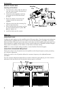
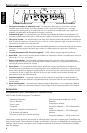
DESIGN FEATURES
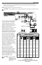
INSTALLATION
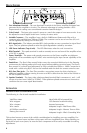
1. Cast Aluminum Heatsink – The cast aluminum heatsink of the Power amplifier dissipates heat
generated by the amplifier's circuitry. The inherent advantage of casting provides a 30%
improvement of cooling over conventional extrusion heatsink designs.
2. Gain Control – The input gain control is preset to match the output of most source units. It can
be adjusted to match output levels from a variety of source units.
3.
Variable Crossover – The amplifiers have a built-in 24dB/octave Butterworth filter with a
crossover point variable from 50Hz to 250Hz. The crossover can be set to Low-Pass (LP) or it
can be bypassed by setting it to All Pass (AP).
4. RCA Input Jacks – The industry standard RCA jacks provide an easy connection for signal level
input. They are platinum-plated to resist the signal degradation caused by corrosion.
5. LED Power Indicator (Top of unit) – The LED illuminates when the unit is turned on.
6. REM Terminal – This spade terminal is used to remotely turn-on and turn-off the amplifier when
+12V DC is applied.
7. Power Terminals – The power and ground connectors on the Power amplifier are platinum-
plated and will accommodate up to 8 AWG wire maximizing the input current capability of the
amplifier.
8. Punch Bass – The Punch Bass control helps correct for acoustical deficiencies in the listening
environment by helping produce full range sound without adding excessive boost. The Punch
Bass control is a narrow band adjustment at 45Hz variable from 0dB to + 18dB. Connection is
made with a cable using RJ-45 and can be installed under the dash for remote control access.
9. RCA Pass-Thru Jacks – The Pass-Thru provides a convenient source for daisy-chaining an
additional amplifier without running an extra set of RCA cables from the front of the vehicle to
the rear amplifier location.
10. Speaker Terminals – The heavy duty, platinum-plated terminal block connectors (+ and –) will
accept wire sizes from 8 AWG to 18 AWG. These platinum-plated connectors are immune to
corrosion that can cause signal deterioration.
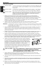
INSTALLATION CONSIDERATIONS
The following is a list of tools needed for installation:
Volt/Ohm Meter
Wire strippers
Wire crimpers
Wire cutters
#2 Phillips screwdriver
Battery post wrench
Hand held drill w/assorted bits
1/8" diameter heatshrink tubing
Assorted connectors
Adequate Length—Red Power Wire
Adequate Length—Remote Turn-on Wire
Adequate Length—Black Grounding Wire
This section focuses on some of the vehicle considerations for installing your new amplifier. Pre-
planning your system layout and best wiring routes will save installation time. When deciding on
the layout of your new system, be sure that each component will be easily accessible for making
adjustments.