Chapter 4. Board Layout
4.1. Component Layout
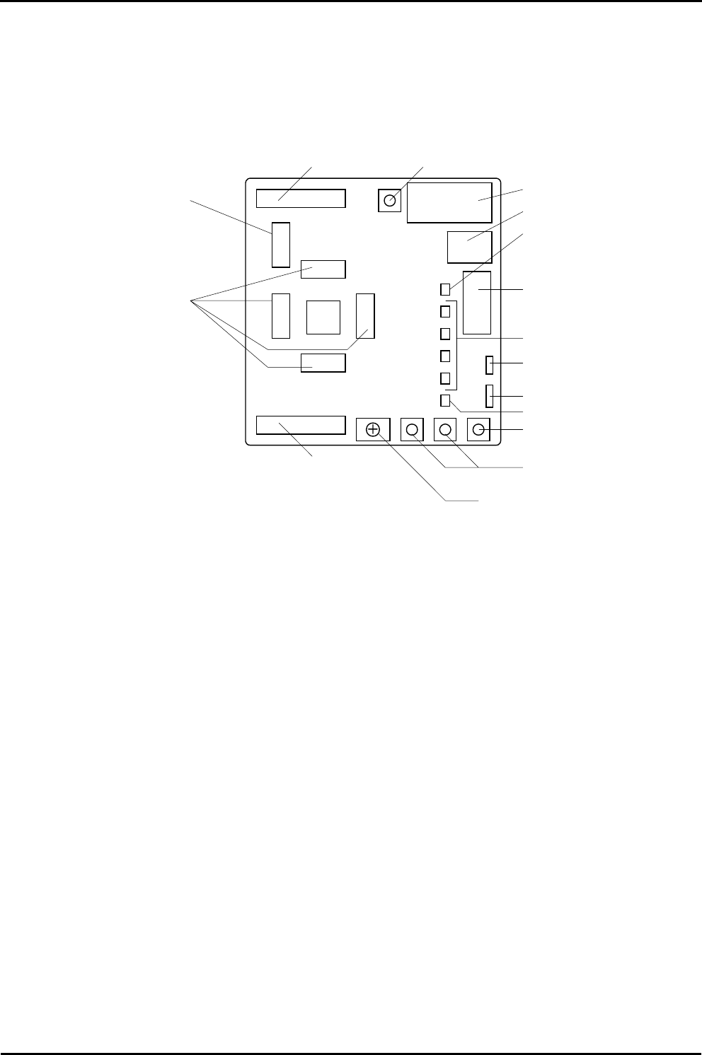
The following diagram shows the top layer component layout of the board.
JA2
JA1
MCU
Reset Switch
E8 Heade
r
User Switches
Potentiomete
r
User LED
Power LED
Boot LED
Power
A
pplication Board Interface
Microcontroller Pin Headers
(J1 to J4)
LCD Display
A
pplication Board Interface
RS232 Serial
User/Boot Switch
LIN Connecto
r
Power Connecto
r
for LIN
Figure 4-1: Board Layout
4


