CONTROLS: REI
7. When the Line Bias Generator is turned off, the voltage meter can measure both AC
and DC volts (Note: AC volts are read as RMS values).
Note: When the Line Bias Generator is turned on, the voltage meter will measure a
combination of the voltage in the circuit that the test leads are connected to and the
voltage presented from the Bias Generator. To read only the Bias Generator, remove
the Test Leads from any circuit.
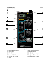
8. The red colored Input Attenuation Indicator will indicate that the input signal is of
sufficiently high level to automatically initiate the input attenuation circuit. This
important function provides attenuation to a high power audio signal so that the gain
circuit will not distort the signal. This automatic attenuator circuit provides
attenuation for audio levels between 300 millivolts and 31 volts. For signals that
exceed 31volts peak-to-peak, distortion will occur.
9. A yellow Line Bias Indicator will indicate the Bias Generator is turned on.
10. The Line Bias Switch will turn the Bias Generator on or off.
11. The Line Bias Voltage Adjust will control the magnitude of the bias voltage. The
mid-position will generate 0V. Turn to the left to generate a negative voltage and
turn to the right to generate a positive voltage. This function is provided specifically
to provide DC voltage to power a potential threat such as an electret microphone or
wiretap device that may be connected to a line. By activating a potential threat, it is
much easier to identify.
12. The Headphone Gain is a volume level control for both the Headphones and the Line
Out. This level control provides up to 15 dB of additional gain.
13. The Headphone Jack is for use with the included headphones.
USING THE CMA: REI
Testing for Voltage levels
Unknown wiring should first be evaluated using a voltmeter to ensure that the voltage
does not exceed the ability of the CMA. However, if the wiring is known to be low-
voltage wiring such as Telephone, LAN system, or security system wiring, then the CMA
can be connected directly to the wiring using the CMA test leads and voltage levels will
be displayed directly on the CMA.


