CONTROLS: REI
IDENTIFICATION
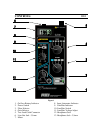
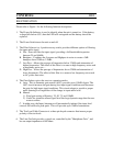
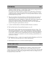
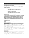
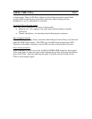
Please refer to Figure 1 for the following function descriptions.
1. The Power On Indicator is used to identify when the unit is turned on. If the battery
voltage falls below 6.9V, then the LED will extinguish and the battery should be
replaced.
2. The Power Switch turns the unit on and off.
3. The Filter Selector is a 4 position rotary switch, provides different options of filtering
the input audio signal.
A. Flat - Does not filter the input signal, providing a full bandwidth inspection
between 25 and 44kHz.
B. Bandpass - Combines the Lowpass and Highpass in series to create a 3dB
bandpass from 320Hz to 3.2kHz.
C. Low Pass - Allows the passage of frequencies below 3.2kHz and attenuation of
higher frequencies. The effect of this filter is to remove high frequency noise such
as machinery noise, etc…
D. High Pass - Allows the passage of frequencies above 320Hz and attenuation of
lower frequencies. The effect of this filter is to remove low frequency noise such
as AC power line noise.
4. The Gain Selector gives the user two operation modes.
A. Auto - This is automatic gain control (AGC) provides up to 105dB of gain. The
AGC circuit increases the gain during low input signal conditions and decreases
the gain for high input signal conditions. This circuit adapts to provide a proper
audio listening level regardless of the change in input audio level.
B. Manual
1.) Fixed gain setting of 0(unity), 25, 50, 75, and 100dB.
2.) Useful for situations where signal level has large dynamic range that the user
wants to utilize.
C. In either case, the Input Attenuator will automatically initiate if the input level
exceeds 300 millivolts peak-peak. This will provide up to 30dB of attenuation.
5. The Test Lead Cable Connector is a three-pin keyed connector that insures proper
polarity of the test leads.
6. The Line Out Jack provides a signal out, controlled by the "Headphone Gain ", and
has an output impedance of 600 ohms.


