


- 11 -
TR-127GK/DX
CHAPTER 4
ALIGNMENT
4.0 REQUIRED TEST EQUIPMENT
c DC Power Supply (13.8VDC, 10A)
d RF Wattmeter (10W)
e Multi-meter
f Automatic Modulation Meter
g Audio Signal Generator
h Frequency Counter (100 MHz)
i RF Signal Generator (100 MHz)
j Automatic Distortion Meter
k Oscilloscope (50 MHz)
l Sinad Meter
4.1 ALIGNMENT PROCEDURES
This transceiver has been aligned at the factory and does not require any adjustments at installation.
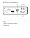
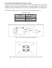
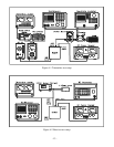
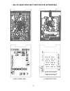
The required test equipment listed are used for the test setup or alignment shown in Figure 4-1
Transmitter Test Setup and Figure 4-2 Receiver Test Setup. These test setups are used in part or total
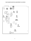
during the following adjustments. Refer to page 14 for adjustment locations.
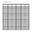
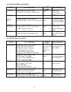
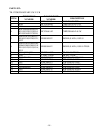
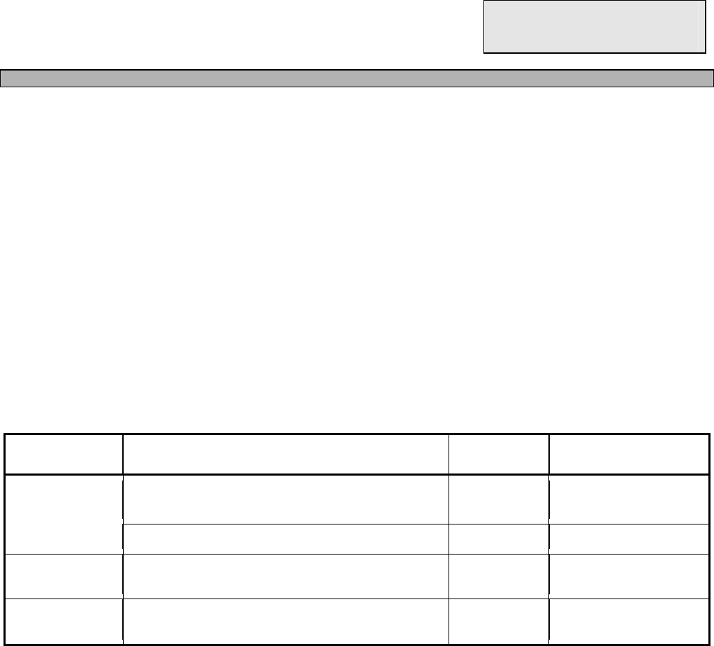
4.1.1 PLL ALIGNMENT
ITEM U.U.T. SETTING
ADJUST
POINT
MEASUREMENT
VCO Set radio to CH 1 AM RX mode.
Connect Multi-meter to TP9.
L23
2.5 VDC ± 0.1
Connect Oscilloscope to TP3. L24 Adjust for max.
AM Frequency Set radio to CH 19 AM RX mode.
Connect Frequency Counter to TP3.
L29
16.4900MHz ± 20Hz
AM OSC Set radio to CH 19 AM TX mode.
Connect Frequency Counter to TP5.
L23
10.6950MHz ± 10Hz