


- 9 -
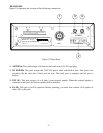
TR-127GK/DX
CHAPTER 3
CIRCUIT
DESCRIPTION
3.0 INTRODUCTION
This section explains the technical theory of operation for the TR-127GK or TR-127DX mobile CB
radio.
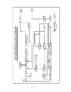
3.1 PLL CIRCUIT
The Phase Lock Loop (PLL) circuit is responsible for developing the receiver’s first local oscillator
signal and the transmitter’s exciter signal. The PLL circuit consists primarily of IC2, IC3, and Q23. The
PLL circuit is programmed by the rotary channel switch GPS-668. The GPS-668 communicates the
correct binary data information to the programmable divider inside of IC2. IC2 then controls the VCO
(Voltage Controlled Oscillator) to oscillate on the correct frequency. This signal is fed either into the
receiver’s first mixer (for receive operation) or the transmitter’s mixer (for transmit operation).
3.2 RECEIVER CIRCUIT
The incoming RF signal comes into the radio via the antenna and into the front-end pre-amp, Q12. The
RF signal is fed into the mixer circuit of Q13 and then into the AM IF section of the receiver. The
signal is then detected by the AM detector and then fed to the audio amplifier section of the receiver
and finally out to the speaker.
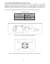
3.3 TRANSMITTER MODULATION CIRCUIT
(1) The transmitter modulation circuit modulates the low-level RF signal from the PLL exciter circuit
with the user’s audio voice signal from the microphone. The audio from the microphone is then
amplified and fed into the transmit amplifier circuit.
(2) The AF power amplifier modulates the last RF amplifier, which produces a true amplitude
modulated RF signal.
3.4 TRANSMITTER AMPLIFIER CIRCUIT
The transmitter takes the basic exciter signal from IC4 of the TX mixer and amplifies it through a series
of amplifiers consisting of Q18, Q17 and Q16 where it is sent out to the antenna connector.