


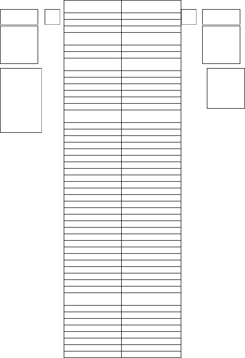
E I
VOLTAGE CURRENT
BOTTOM
AND TOP
TEST
JACKS
MIDDLE
AND BOT
TEST
JACKS
1.00 VOLT
EQUALS
100 MILLI
AMPS AC-
TUAL CUR-
READINGS
NEEDED
THAT PRO-
DUCE 100
MILLIWATTS
1.0
1.00
1.1 .910
1.2 .840
1.3 .770
1.4
.720
1.5 .670
1.6 .630
1.7
.590
1.8 .560
1.9 .530
2.0 .500
2.1 .480
2.2 .455
2.3 .435
2.4
.420
2.5 .400
2.6 .385
2.7 .370
2.8 .360
2.9 .345
3.0 .335
3.1 .325
3.2 .315
3.3 .305
3.4 .295
3.5 .285
3.6 .280
3.7 .270
3.8 .265
3.9 .255
4.0 .250
4.1 .245
4.2 .240
4.3 .233
4.4 .228
4.5 .223
4.6 .218
4.7 .213
4.8 .210
4.9 .205
5.0 .200
5.1
.197
5.2 .193
5.3 .189
5.4 .186
5.5 .183
5.6 .180
5.7 .177
5.8 .174
5.9 .171
Please
Note!! Do
not use
this man-
ual
method,
for refer-
ence
only!!
Simply ro-
tate power
control un-
til you get
the “green
light”!!
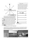
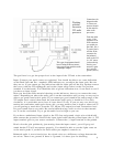
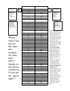
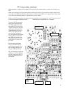
The manual method in-
volves simply involves
taking 2 voltage readings
and referring to the
power chart in this man-
ual. Adjust the power pot
until you are at the legal
power level. Turn
the audio pot all the way
down. Take your voltage
reading, take this reading
with the meter
leads in the same posi-
tion as when you were
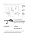
tuning. Now place your
Black (negative) test
lead in the bottom test
hole pad & your Red
(Positive) test lead in the
middle test hole pad.
This will measure your
Current.
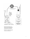
Your power should not
exceed 100 milliwatts
or .1 Watt to comply
with FCC rules (Part 15).
See the conversion table
supplied for different
combinations of
Voltage and Current that
equal 100 milliwatts. The
“Power Adjust” works
just like a volume
control. Clockwise is
more power and counter
clockwise is less. Again
with the AM1000T
“Green light” simply
adjust Power level con-
trol until the LED is
green.
13