


SHA1 • 12
ASSEMBLING THE SHA1 HEADPHONE AMPLIFIERS:
Sort out all of your parts to begin with, making sure you have all
of the parts required. You can use old egg cartons to hold
various parts to make them easier to find. Make sure to mount
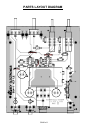
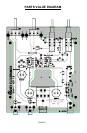
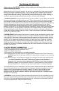
parts on the correct side! You will want to use the parts layout
diagram to assist you in finding where the parts go.
1. Orient the board in the same direction as the parts layout
diagram.
2. Install C12, a .01uF ceramic capacitor (Marked .01, 10n,
or 103)
3. Install C14, another .01uF ceramic capacitor (Marked .01,
10n, or 103).
4. Install R2, a 4.7K ohm resistor (yellow-violet-red).
5. Install R7, another 4.7K ohm resistor (yellow-violet-red).
6. Using a scrap piece of component lead, install JMP2.
These jumpers act as “bridges” over other connections,
allowing us to create a well routed PC board.
7. Using another scrap component lead, install JMP1.
8. Install C10, a .01uF ceramic capacitor (Marked .01, 10n,
or 103).
9. Install C8, another .01uF ceramic capacitor (Marked
10n, .01, or 103).
10. Install D1, the 1N4002 rectifier diode. Make sure and
install the lined end (cathode) of the diode in the same
direction as shown in the diagram. This diode prevents us
from accidentally charging an installed battery while external
power is applied.