


QAMP20 • 9
These last four parts (R8,9 and C11,12) form parasitic suppression networks
across each transistor to suppress any tendency for high frequency oscillation
in the power amplifier.
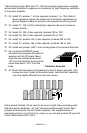
32. Install C3, another .1 µf disc capacitor (marked .1 or 104). Both of
these capacitors bypass the center tap of the ferrite transformers to
ground. Bypass means to provide a low impedance path to ground.
33. Install C1, 100 to 220 µf electrolytic capacitor. Be sure to observe
correct polarity.
34. Install C4, 180 ρf disc capacitor (marked 180 or 181).
35. Install C5, 330 ρf disc capacitor (marked 330 or 331).
36. Install C6, another 330 ρf disc capacitor (marked 330 or 331).
37. Install C7, another 180 ρf disc capacitor (marked 180 or 181).
38. Install wire jumper, JMP1. Use a scrap piece of component lead wire.
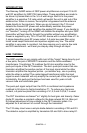
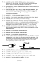
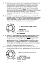
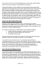
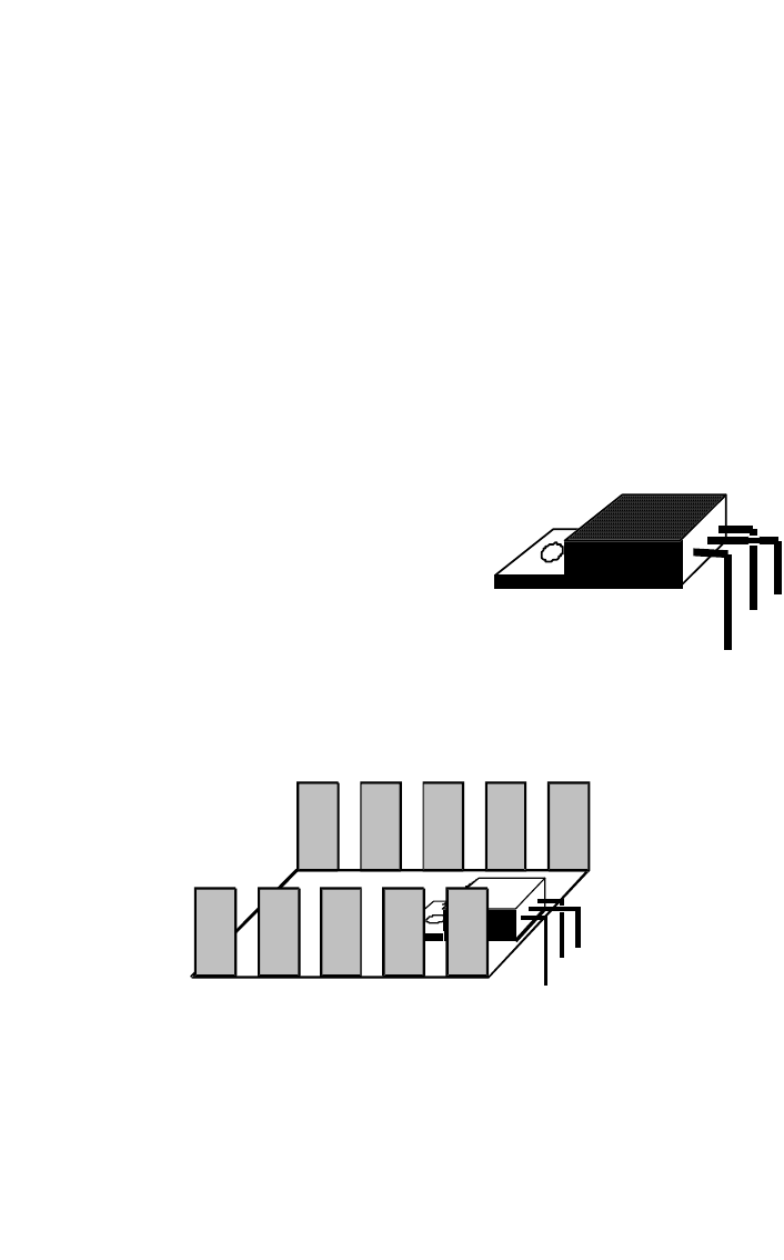
39. Locate the MOSFET power
transistors and prepare the leads for
insertion into the PC board. Bend
down the two outside leads about
1/8" from the transistor body and the
center lead about 3/16" from the
body.
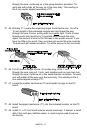
40. Mount the transistors and heatsinks to the PC board using the 4-40
screws and nuts. Solder all transistor leads. Note that the heatsinks
may look slightly different from the ones shown.
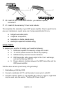
We're almost finished. All we need to do now is install a few remaining parts
that have to be handmade - for that "old-world craftsmanship" touch! We'll
prepare all those parts now for further assembly. We supplied plenty of
enameled wire for your kit but if you mess up, you can get a whole 50' spool of
it from Radio Shack (278-1341).
Transistor bend pix