


QAMP20 • 15
KB4ZGC on how to make a highly accurate yet inexpensive dummy load and
wattmeter capable of showing 1/10-watt differences in RF power. If you use a
wattmeter characterized for the HF frequency region, it will not give accurate
results at the much higher two meter frequencies, although it will be quite
adequate for go/no-go testing.
MAXIMIZING RF POWER OUTPUT
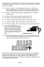
The simplest way to ensure maximum reasonable power output without
component damage is to run the DC voltage in the 13 to 14 volt range,
observing a maximum limit of +15VDC. Typically, an automobile power source
is 13.6 volts when the engine is running, and most mobile rigs are specified at
this voltage level.
IMPORTANT NOTE: If you are experimenting with this transmitter and see a
sudden and massive increase in power output and DC current, you have not
reached the promised land or created a 100 watt amplifier! Sudden surges like
that are a sure sign of amplifier self-oscillation. Kill the DC power supply
immediately because your RF power transistors are heading to self-destruction
while probably interfering with every TV set in the neighborhood! A poorly
matched antenna along with higher supply voltages is usually responsible for
this occurring. Any prolonged "parasitic" emissions may also overheat and
destroy other components in the amplifier.
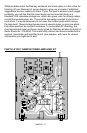
TROUBLESHOOTING HINTS
The QRP power amplifier is very straight forward and simple to troubleshoot.
When beginning to track down a problem, use some common sense to narrow
down your search area.
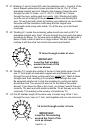
If the amplifier is not keying upon application of RF power, check to see if the T-
R relay circuitry is operating. A quick read-over of the theory of operation tells
us the diode detector senses the RF and a pair of transistors amplifies the
signal to activate the T-R relay. Proper logic tells us to: 1) First check and see if
RF is getting to the diodes; 2) see if they are detecting RF; 3) see if the
transistors are driving the relay. Proper procedure is to take just one part of the
circuit at a time and follow the signal through.
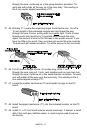
If the amplifier does not amplify, check to see if RF is flowing through to
transformer T2 and across to the RF power transistors. Amplified output should
appear at output transformer T1 and then on to the low pass filter. Remember
that RF enters and exits through relay contacts on K1.
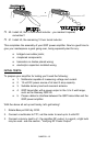
Do the transistors get too hot? Do they get hot without amplifying? Things to
check are the bias circuitry and RF path through the relay. The amplifier should
draw about ¼ amp with no signal applied. If you see more than that, recheck
the bias setting (see the section "INITIAL TESTS").