


MR6 • 7
MR6 PARTS LIST Note the extra chip components included.
RESISTORS
4 1K ohm chip resistors (R2,3,4)
3 10K ohm chip resistors (R1,7)
7 100K ohm chip resistor (R5,6,8,9,10)
CAPACITORS
7 5 pF chip capacitors (C7,8,9,11)
2 22 pF chip capacitor (C12)
3 100 pF chip capacitor (C3,4)
3 .001 uF chip capacitor (C2,10)
3 .1 uF chip capacitor (C5,6)
1 10 uF electrolytic chip capacitor (C1)
SEMICONDUCTORS
3 MMBTH10L chip NPN transistors [marked 3E] (Q3,4)
4 MMBTA20L chip NPN transistors [marked 1C] (Q1,2,5)
2 MMBV2109 chip varactor diode [marked 4J] (D1)
INDUCTORS
1 .10 uH chip inductor [marked R10 or 101K - in tiny letters!] (L2)
1 .15 uH chip inductor [marked 151K - in tiny letters!] (L1)
MISCELLANEOUS PARTS AND HARDWARE
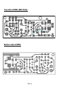
1 MR6 printed circuit board
1 3 Volt Lithium camera battery
1 Battery holder (BH1)
1 Crystal, 12, 16 or 24 MHz (Y1)
18 inches insulated wire for antenna lead