


MR6 • 5
RAMSEY Learn-As-You-Build KIT ASSEMBLY
There are numerous solder connections on the MR6 printed circuit board.
Therefore, PLEASE take us seriously when we say that good soldering is
essential to the proper operation of your transmitter!
• Use a 25-50 watt soldering pencil with a clean, sharp tip.
• Use only rosin-core solder intended for electronics use.
• Use bright lighting, a magnifying lamp or bench-style magnifier may
be helpful.
• Do your work in stages, taking breaks to check your work. Brush
away wire cuttings so they don't lodge between solder connections.
We have a two-fold "strategy" for the order of the following kit assembly
steps. First, we install parts in physical relationship to each other, so there's
minimal chance of placing parts on the wrong pads. Second, whenever
possible, we install in an order that fits our "Learn-As-You Build" Kit building
philosophy.
For each part, our word "Install" always means these steps:
1. Pick the correct part value to start with.
2. Place it on to the correct PC board location.
3. Orient it correctly, follow the PC board drawing and the written
directions for all parts - especially when there's a right way
and a wrong way to solder it in. (Diode bands, electrolytic
capacitor polarity, transistor shapes, dotted or notched ends
of IC's, and so forth.)
4. Solder all connections unless directed otherwise. Use enough heat
and solder flow for clean, shiny, completed connections.
SURFACE MOUNT COMPONENT SOLDERING INSTRUCTIONS:
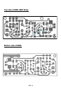
You’ll notice that the circuit board contains only a few holes for component
leads to pass through. This is because the SMT components will be affixed to
the “solder” side of the PC board, the side that contains the PC traces. Be
aware that the component view for assembly is looking at the solder side of
the PC board.
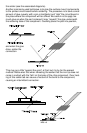
Patience is the key when installing surface mount components. Typically, the
first step (after identifying the component) is to “tin” one of the PC traces that
will connect to the part. Once this is accomplished, the part can be installed
by holding it with tweezers in contact with the “tinned” trace and re-heating