


HR40 • 17
A better operating arrangement will consist of a T-R switch, either a manual
switch or break-in delay relay circuit. This switching circuit can disconnect the
SA602 audio output at the volume control, and switch in a pleasant oscillator
pitch (keying sidetone) which is amplified to listening level by LM386. The
Ramsey Electronics Universal timer kit No. UT-5 is easily adapted as a
sidetone oscillator.
• SPEAKER OPERATION
A fifty cent, two inch diameter speaker, lying naked on your workbench will
give you a fair test of the speaker output capability. Speaker quality and well-
designed enclosures have their clear purposes! A reasonable speaker in a
box delivers a pleasant listening volume. On the other hand, the LM386
indeed can deliver more audio output punch than is developed in our HR-
series kits. For example, our FM receivers, using the same LM386 audio IC,
deliver more volume. These receivers, however, take advantage of IF
amplifiers, drift-compensation and crystal controlled oscillators built into mass
production, sophisticated FM receiver ICs. A heavier drain on the HR40’s
battery by stronger audio will quickly result in chirpy signals and oscillator drift
as well as the need for frequent battery replacement. Remember the SA602
circuits similar to Ramsey’s generally call for sets of C or D cell batteries! For
Experienced Builders more information regarding audio output is in the
general notes.
The simple design of the audio stage of the Ramsey HR40 receiver assumes
preference for headphone or small speaker operation, low battery drain and
general economy.
• MORE AUDIO POWER - ANOTHER WAY
If you want to use your HR40 for casual band monitoring while you are busy
across the room, in the shop, or to share with a class or club, and want LOTS
more volume, try building up our very inexpensive Ramsey BN-9, 2 watt
general purpose amplifier kit. Supply DC voltage to such an amplifier
separately, using D-cells, a lantern or auto battery, or a well filtered power
supply.
• ADDING AN LED POWER ON INDICATOR
For many people, a pilot lamp to indicate “power on” is more than a nice
touch. They expect it and depend on it , reminding us that “real radios glow in
the dark!”
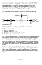
Adding a simple LED power-on indicator to your Ramsey HR40 is easy. All
you need is the LED itself and a small 1K or 2.2K resistor. Study the PC
traces between the positive battery supply wire and the on-off switch. The
unused connectors on top of your switch are an ideal point to get the + DC
voltage needed for the anode (longer lead) of the LED. Plan where and how