


FT146 • 16
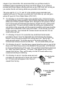
The "legs" or leads for inserting L2, L7, L3 and L4 should be about " long.
These coils should sit about 1/8" maximum above the PC board when soldered.
❒ 80. Install L12, one of the small 3 turn ferrite bead RF chokes you wound.
Pull it up snug against the PC board and solder.
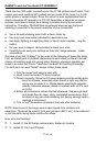
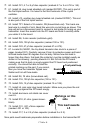
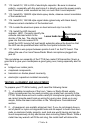
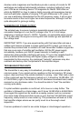
❒ 81. Install TP2, another test point. Select a 1K resistor, R2 (brown-black-
red). Trim back one lead wire to a length of inch. Bend this wire into a
small loop as shown. This loop acts as a convenient point to connect a test
probe for tuning up your transmitter. Insert the resistor into the PC board
and hold it carefully while you solder it to
the board.
❒ 82. Install C18, 22 pf disc capacitor
(marked 22 or 22K).
❒ 83. Install C10, 47 pf disc capacitor (marked 47 or 47K).
❒ 84. Install Q5, 2N3866 metal can RF transistor. Be sure you press the
transistor case flush against the PC board and solder securely.
❒ 85. Install L6, a 6 hole ferrite bead choke wound previously.
❒ 86. Install C4, .01 uf disc capacitor (marked .01 or 10 nf or 103).
❒ 87. Install L11, pink slug tuned coil.
❒ 88. Install aluminum shield can cover over L11.
❒ 89. Install C19, 10 pf disc capacitor (marked 10 or 10K).
❒ 90. Install C20, another 10 pf disc capacitor.
❒ 91. Install L7, a 1 turn coil wound previously. Ensure that the coil is seated
flush against the PC board and not mounted with long leads up in the air -
which would add undesired additional inductance.
❒ 92. Install C11, 100 pf disc capacitor (marked 100 or 101).
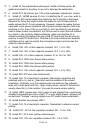
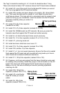
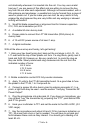
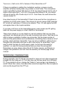
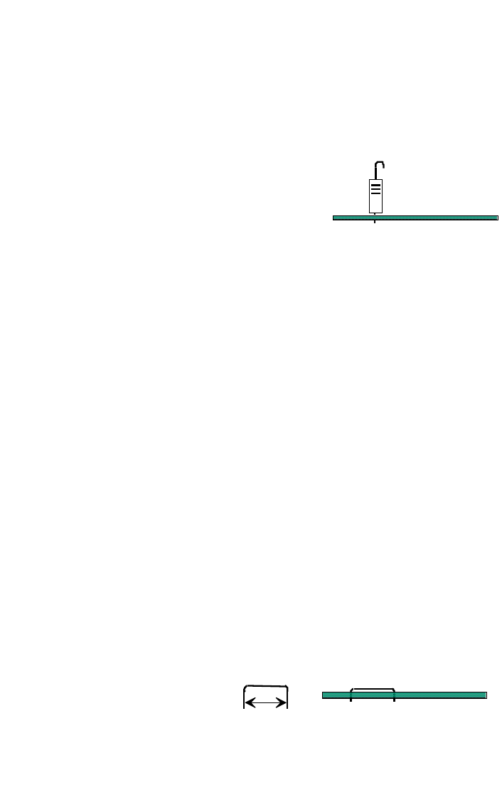
❒ 93. Prepare a inch long wire jumper from the heavy tinned bus wire used
for winding coils previously. Install this jumper in the L8 location on the PC
board. This wire must sit flat against the PC board and not up above.
Believe it or not, this wire is actually an inductor providing inpedance
matching into Q6.
❒ 94. Install C26, 100 pf disc
capacitor (marked 100 or 101).
❒ 95. Install L10, small ferrite
bead RF choke you wound
earlier.
❒ 96. Install C6, 100 pf disc
capacitor (marked 100 or 101).
Heavy buss
wire jumper
(not a scrap component lead)
1/2 inch
PC board
Wire sits flat
against board
Resistor
PC board
Test point loop