


FT146 • 12
❒ 60. Install C21, 4.7 or 5 pf disc capacitor (marked 4.7 or 5 or 4.7K or 5K).
❒ 61. Install L9, slug tuned shielded coil (marked 007007). This coil is part of
the first tripler section. It is tuned to the third harmonic of the crystal
oscillator.
❒ 62. Install L13, another slug tuned shielded coil (marked 007007). This coil
is also part of the first tripler section.
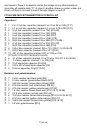
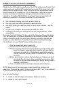
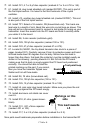
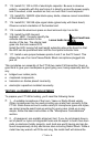
❒ 63. Install TP1. Select a 1K resistor, R9 (brown-black-red). Trim back one
lead wire to a length of inch. Bend this wire into a small loop as shown. This
loop will act as a convenient point to connect a test probe for tuning up your
transmitter. Insert the resistor into the PC board and hold it carefully while
you solder it to the board.
❒ 64. Install R6, 2 ohm resistor (red-black-gold).
❒ 65. Install C29, 100 pf disc capacitor (marked 100 or 101).
❒ 66. Install C22, 47 pf disc capacitor (marked 47 or 47K).
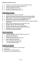
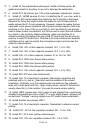
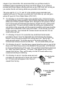
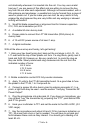
❒ 67. Locate Q4, NE021, the tiny black transistor disc stuck to a piece of
paper (marked 021). Carefully remove it from its protective paper and bend
all three leads down 90 degrees from its body. Notice how one lead is
longer than the others, that lead (the collector) must be installed exactly as
shown in the drawing - pointing towards L5. Set Q4 into the PC board
making sure that its body is snugly against the PC board and positioned
correctly. You should be able to read the
printed markings on the part, if you cannot,
then you have the transistor flipped over.
Solder and trim all three leads.
❒ 68. Install R4, 1K ohm (brown-black-red).
❒ 69. Install C16, 100 pf disc capacitor (100 or 101).
❒ 70. Install C25, 12 pf disc capacitor (marked 12 or 12K).
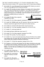
❒ 71. Install L5, pink color slug tuned inductor. Make sure you place the coil
body right up against the PC board snugly.
❒ 72. Install aluminum coil shield can cover
over L5.
❒ 73. Install R10, 51 ohm (green-brown-
black).
❒ 74. Install C31, .001 uf disc capacitor
(marked .001 or 102).
❒ 75. Install C17, 2 or 2.2 pf disc capacitor (marked 2 or 2.2).
Nine parts need handmade preparation before installation in the transmitter RF
021
K24
This lead towards
L5
Markings on this
side
Resistor
PC board
Test point loop