


FR6 • 6
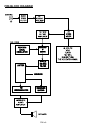
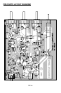
practical level for speaker or headphone operation. Pin 16 of U2 will ground
the input of U3 when the squelch is closed.
L4, a 450 KHz IF coil, permits adjustment of the 90-degree voltage-current
phasing ("quadrature") of FL2's output to the FM detector demodulator (pin 8
of the MC3359).
PARTS LIST
Inductors
2 .15 uH inductors [looks like a resistor with brown-green-silver
bands] (L1,L2)
1 slug-tuned turn coil [blue color] (L3)
1 shielded transformer coil [marked LB 53303] (L4)
Semiconductors and IC's
1 2SC2498 or 2SC2570A transistor (Q1)
3 2N3904 transistor (Q2,Q3,Q4)
1 SA602 8-pin IC (U1)
1 MC3359 18-pin FM receiver IC (U2)
1 LM386 8-pin audio amplifier IC (U3)
1 Varactor diode, BB505 [orange body marked BB505] (D1)
1 1N4148 signal diode (D2)
Special Components
1 10.24 MHz Crystal (Y1)
1 10.7 MHz ceramic filter [brown, molded, 3 leads] (FL1)
1 450 KHz ceramic filter [black, square] (FL2)
Fixed Resistors
1 2 ohm [red-black-gold] (R22)
3 270 ohm [red-violet-brown] (R6,9,20)
1 470 ohm [yellow-violet-brown] (R5)
2 1K ohm [brown-black-red] (R11,12)
3 10K ohm [brown-black-orange] (R7,17,19)
1 18K ohm [brown-gray-orange] (R18)
1 33K ohm [orange-orange-orange] (R14)
4 47K ohm [yellow-violet-orange] (R4,8,13,21)
1 100K ohm [brown-black-yellow] (R16)
1 470K ohm [yellow-violet-yellow] (R15)
1 1 megohm [brown-black-green] (R10)
Capacitors
1 4.7 or 5 pF (C2)
2 10 pF (C1,5)
1 22 pF (C19)