


FR146 • 16
4. MC3359 FM IC and ASSOCIATED COMPONENTS
❒ 55. Install R17, 10K ohms [brown-black-orange]
❒ 56. Install R14, 33K ohms [orange-orange-orange]
❒ 57. Install C24, .001 uF [marked .001, 102, or 1 nF].
❒ 58. Install C25, .001 uF [marked .001, 102, or 1 nF].
❒ 59. Install C26, .01 uF [marked .01, 103, 10 nF].
❒ 60. Install L4, the 455 KHz quadrature coil [marked LB53303], soldering
the two pins and the two mounting tabs.
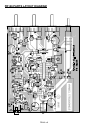
❒ 61. Install MC3359 IC, U2. As in the case of the SA602 IC, you could
choose to install an 18-pin IC socket rather than soldering the IC directly.
Re-read the discussion of IC sockets offered for the installation of U1.
Larger IC's such as the MC3359 require considerably more care in socket
insertion. Notice that the end of the IC marked by a band, dot, or notch
must be oriented correctly as shown on the parts layout diagram. Solder
each of the 18 connections carefully. Make sure you have good lighting as
well as good technique to make sure that no solder "bridges" flow
between the connections.
❒ 62. Install C22, 100 pF (marked 100, 101, or 101K).
❒ 63. Install C16, .01 uF [marked .01 or 103 or 10 nF].
❒ 64. Install C17, .01 uF [marked .01 or 103 or 10 nF].
❒ 65. Install C21, .01 uF [marked .01 or 103 or 10 nF].
❒ 66. Install C18, 220 pF [marked 220 or 221].
❒ 67. Install C19, 22 pF.
❒ 68. Install Y1, the 10.24 MHz. crystal. No special procedure is required.
Simply press the crystal firmly into its holes as far as it will go, and make
good solder connections.
❒ 69. Install FL2, the 450 KHz filter. Its three leads are delicate and fit in
only one way.
❒ 70. Install C23, .001 uF [marked .001, 102, or 1 nF].
❒ 71. Install C27, 1 uF electrolytic, observe correct polarity.
❒ 72. Install D2, the 1N4148 signal diode, observe correct orientation of the
banded cathode end. Be sure you correctly identified D2 and did not
confuse it with the varactor diode already installed.