


OUTPUT
AC POWER IN
CIRCUIT
BREAKER
CH B
–+
CH A
–+
BRIDGE
–+
GROUND LIFT
GROUND LIFT
GND
INPUTS
CH B CHA
CH B CHA
MONO
STEREO BRIDGE
OUTPUT
AC POWER IN
CIRCUIT
BREAKER
CH B
–+
CH A
–+
BRIDGE
–+
GROUND LIFT
GROUND LIFT
GND
INPUTS
CH B CH A
CH B CH A
MONO
STEREO BRIDGE
OUTPUT
AC POWER IN
CIRCUIT
BREAKER
CH B
–+
CH A
–+
BRIDGE
–+
GROUND LIFT
GROUND LIFT
GND
INPUTS
CH B CH A
CH B CH A
MONO
STEREO BRIDGE
OUTPUT
AC POWER IN
CIRCUIT
BREAKER
CH B
–+
CH A
–+
BRIDGE
–+
GROUND LIFT
GROUND LIFT
GND
INPUTS
CH B CH A
CH B CH A
MONO
STEREO BRIDGE
2 – PYLE PRO PT3200/4000 Amplifier Owner’s Manual PYLE PRO PT3200/4000 Amplifier Owner’s Manual -3
INSTALLATION GUIDELINES
Input connections
These amplifiers accept a broad range of input sources,
including Compact Disc (CD) players; Cassette, Reel-to-Reel
or other tape players; Radio Tuners; Equalizers; Signal
Processors.
Connecting a CD or tape player or tuner
In a normal installation, one would use the RCA JACKS for
connecting a CD player, tape player or tuner.
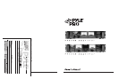
Connecting an equalizer or external signal processor
Connect the processor’s OUT to the amplifier’s INPUT
connectors.
EQ OR MIXER
use XLR/6.35 mm
combo jacks
-OR–
CD PLAYER, TAPE PLAYER
OR TUNER
Connecting the GND (Ground) screw terminal
Connecting a mixer or preamplifier may cause excessive
noise or hum in the amplifier output. To prevent this,
connect one end of a low-capacitance shielded wire to the
amplifier’s ground screw (on the rear panel). Then connect
the other end of this wire to the ground terminal on the
mixer or preamplifier enclosure.
PREAMP OR MIXER
use RCA jacks
LOW CAPACITANCE SHIELDED WIRE
GROUND
SCREW
Speaker connections
You can connect 4 Ohm, 8 Ohm or 16 Ohm speakers to
Channel A and/or Channel B of the amplifier. If you connect
two pairs of speakers, be sure to follow these guidelines:
• Speakers which are connected to the same channel are
part of a pair, and must be of the same impedance.
• Speakers connected to different channels are NOT part
of a pair, and can be of different impedances.
1. Prepare the speaker wire by removing about 1 inch of
insulation from the end of the speaker wire you intend to
connect to the amplifier. Then twist the exposed wire to
secure all the wire strands.
NOTE: Use 16-gauge speaker wire for lengths up to25
feet; 14-gauge wire for lengths over 25 feet. It is
recommended that you use the shortest length of wire
possible.
2. Connect the speaker wires to the speaker's positive and
negative terminals.
NOTE: Most speaker terminals are either color-coded
or have a mark that indicates the terminal's polarity.
Usually positive terminals are red or have a plus symbol
(+), and negative terminals are black or have a minus
symbol (-).
3. Connect the speaker wires to the amplifier's left and
right speaker terminals according to the terminal color
polarity.
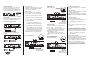
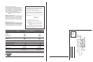
Stereo or Mono Inputs
Your Pyle Pro amplifier can be operated in Stereo, Mono or
Bridged mode, depending on the input source. If the input
signal is mono, slide the Stereo/Mono/Bridged selector
switch to MONO and the signal will be routed through both
channels. If you wish to run the amplifier in bridged output
mode, slide the switch to Bridged.
EQ OR MIXER
Connecting to standard AC power
After making all other connections, set the POWER switch
to OFF position. Then connect the power cord to a standard
AC outlet.
Mounting the amplifier
This amplifier is designed to accept standard rack mounting
installations. Two slots on each end of the front panel make
it suitable for such an installation.
Tightly secure four mounting screws (not supplied) through
these fours slots and into your standard electronics equipment
rack.
Turning the amplifier on
1. Turn on the audio input source equipment which is
connected to the amplifier INPUT jacks.
2. Set the amplifier’s Channel A and Channel B output level
gain controls to the minimum level settings.
3. Push in the power switch to turn the amplifier on.
Using the power meters
The meter pointer position indicates the amplifier output
power. For ease of reading in dark environments, the meter
is illuminated.
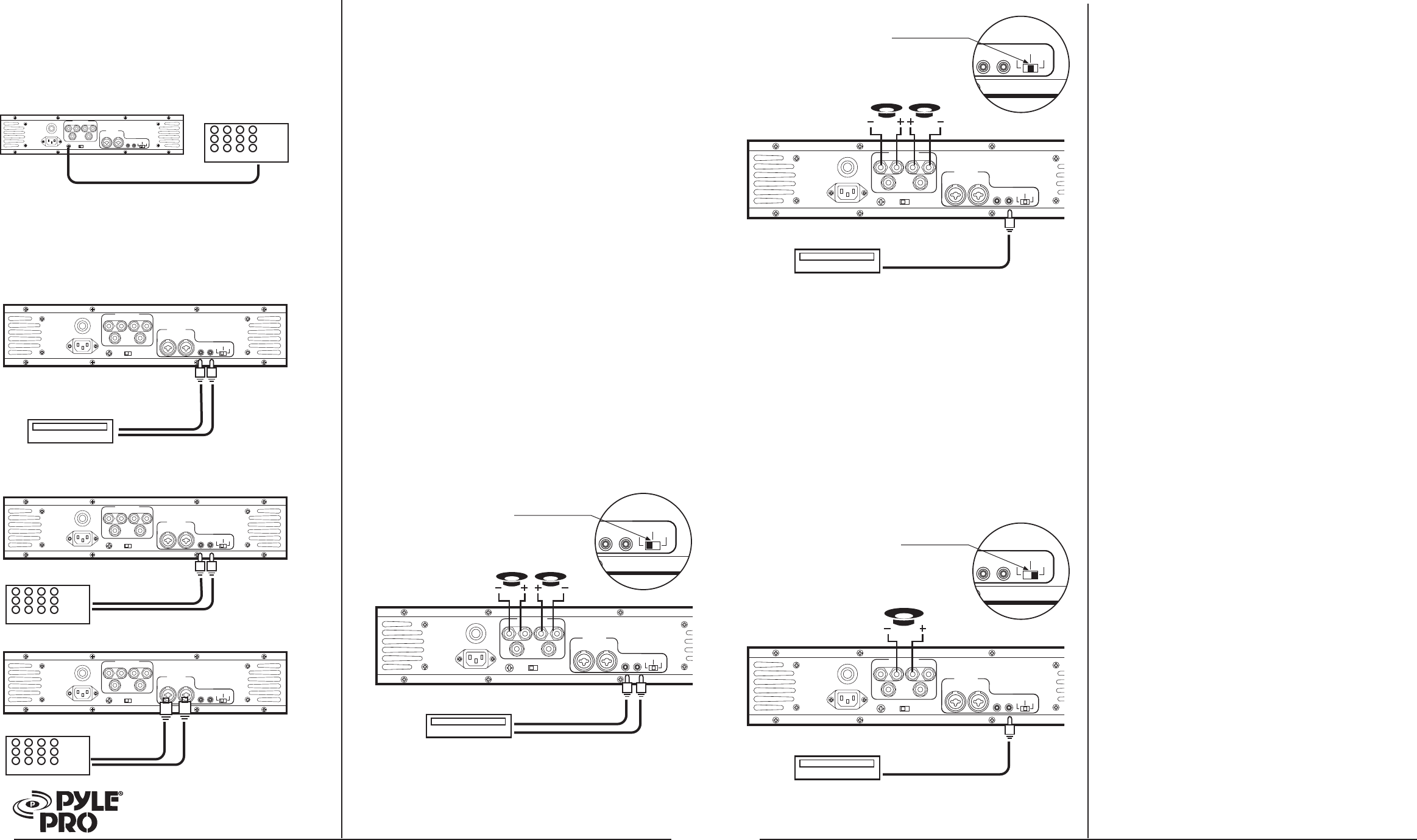
Bridged Mode Operation
This amplifier can operate in a mono bridged output mode, if
your speakers can handle the following power output levels:
PT-3200: 600 watts PT-4000: 800 watts
As shown in the diagram below, connect the speaker's positive
(+) to the amplifier's red speakers left (A/B) terminals and
negative (-) to red speakers right (A/B) terminals.
The speaker right (+) on the amplifier is used as a negative (-)
terminal for a bridged connection.
NOTE: The extra amplifier output of 6.35mm phone
jacks can not be used for the bridged connection. It can only
be used in normal (non-bridged) operation as a stereo speaker
output.
Using the Left and Right Output Level controls
Rotate output level gain clockwise to increase, or counter-
clockwise to decrease the output power. To get the best
performance with the least sound distortion, always adjust
the output level gain so the meter's pointer does not
continuously exceed the extreme right of the meter's scale.
CAUTION: It is possible to overdrive the amplifier by
setting output level gain too high, which may cause
damage or failure.
About the internal clip circuitry
Special clip circuitry incorporated into your Pyle Pro
amplifier’s design protects the amplifier and speaker system
from being damaged from overdriving power.
Under normal conditions, the amplifier’s clip indicator will
flicker as the output power momentarily exceeds the level
as set by the output level gain selector.
However, under excessive output conditions, the clip
indicator lights remain on continuously, alerting you that
the special clip circuitry has become active. When this
occurs, you should simply reduce the output power level
by rotating the Master Volume control counterclockwise.
SWITCH IN “MONO” POSITION
MONO SIGNAL SOURCE
USE
CHANNEL A
INPUT ONLY
MONO OPERATION
SWITCH IN “BRIDGED” POSITION
MONO SIGNAL SOURCE
USE
CHANNEL A
INPUT ONLY
MONO BRIDGED OPERATION
OUTPUT
AC POWER IN
CIRCUIT
BREAKER
CH B
–+
CH A
–+
BRIDGE
–+
GROUND LIFT
GROUND LIFT
GND
INPUTS
CH B CH A
CH B CH A
MONO
STEREO BRIDGE
CH B CH A
MONO
STEREO BRIDGE
CAUTION! Do not use
balanced and unbalanced
inputs simultaneously!!
SWITCH IN “STEREO” POSITION
STEREO SIGNAL SOURCE
OUTPUT
AC POWER IN
CIRCUIT
BREAKER
CH B
–+
CH A
–+
BRIDGE
–+
GROUND LIFT
GROUND LIFT
GND
INPUTS
CH B CH A
CH B CH A
MONO
STEREO BRIDGE
STEREO OPERATION
CH B
CH A
CH B CH A
MONO
STEREO BRIDGE
CAUTION! Do not use
balanced and unbalanced
inputs simultaneously!!
CH B
CH A
OUTPUT
AC POWER IN
CIRCUIT
BREAKER
CH B
–+
CH A
–+
BRIDGE
–+
GROUND LIFT
GROUND LIFT
GND
INPUTS
CH B CH A
CH B CH A
MONO
STEREO BRIDGE
CH B CH A
MONO
STEREO BRIDGE
CAUTION! Do not use
balanced and unbalanced
inputs simultaneously!!
DO NOT USE
BLACK TERMINALS