


7
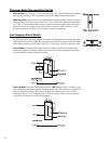
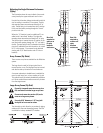
Adjusting the Angle Between Enclosures
(Splay)
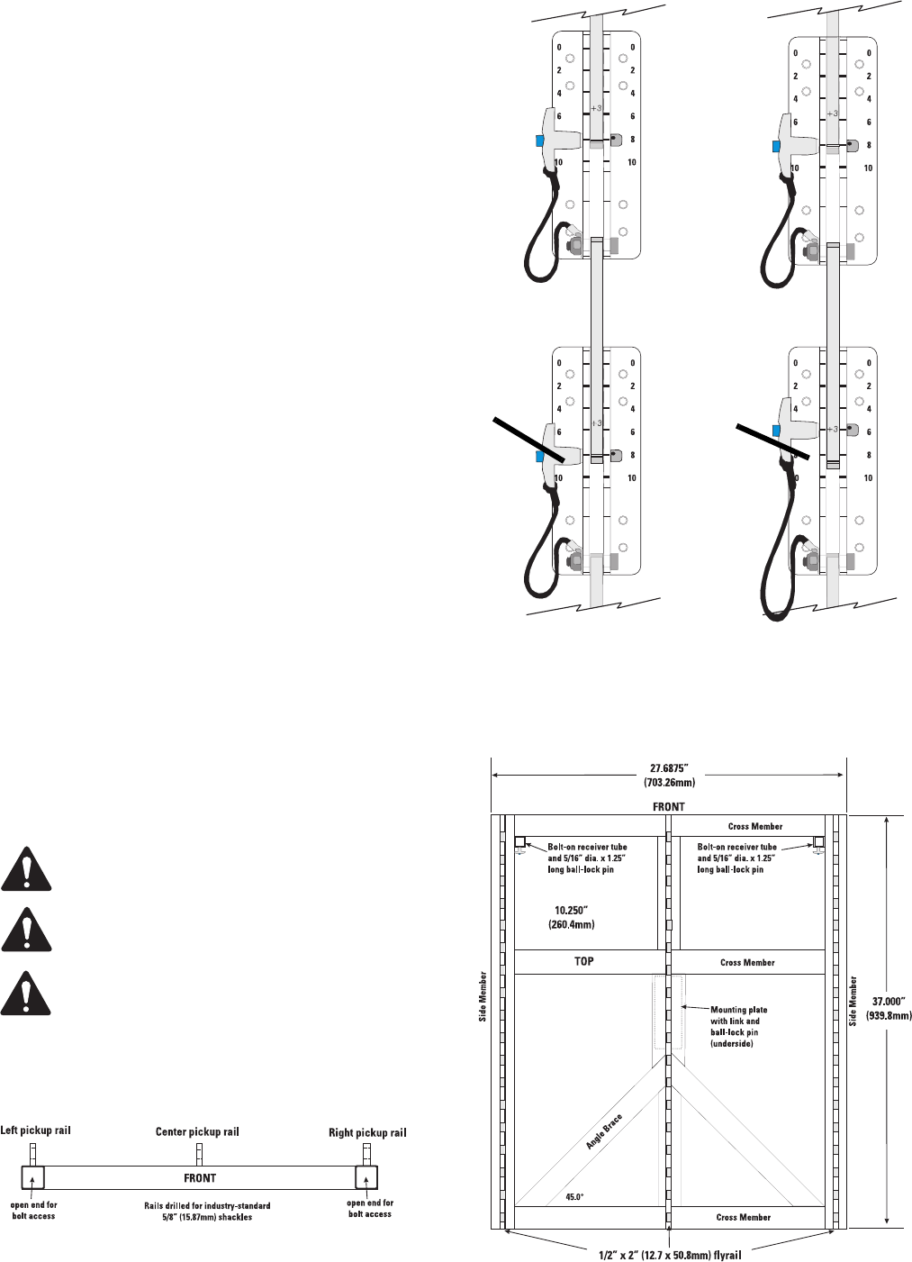
The illustration shows the rear pin block of two enclo-
sures joined by the upper enclosure’s rear link arm.
Use the first pin location (closest to the end) on the link
arm for setting in normalized 2° increments. The left-
side example shows two enclosures linked for 8° of
splay. The ball-lock pin is inserted into the 8° position
in the rear block while passing through the “normal”
pin hole in the link.
When the "+3" location is used, an additional 3° are
added to the "normalized" location. The right side
example shows two enclosures linked for 9° of splay.
The ball-lock pin is inserted into the 6° position in the
rear block while passing through the “+3°” pin hole in
the link. The total splay is the 6° indicated on the block,
plus the 3° additional from the link position, for a total
of 9°. In this manner 1° increments can be attained
starting with 3° (0° block location and +3° link arm
location).
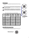
Array Frames (Fly Grids)
There are two array frames available for the WideLine
system.
The large frame is used for flying a typical four to
twenty-four-box array. The large grid may be inverted
and used to stack up to twelve or more enclosures.
A compact and easier to handle frame is available for
use as a small array, four or less, stacking or fly grid.
This grid will easily sit on deck stacked bass enclosures
or it can be used at those smaller events to fly clusters
from the stage trusses.
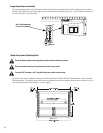
Large Array Frame (Fly Grid)
Do not fly (suspend) more than twenty-four
(24) enclosures form the large array frame.
Do not stack more than twelve (12) enclo-
sures on a large array frame.
Use only 5/16” diameter x 1.25” long ball-
lock pins on front receiver tubes.
The three pick up rails allow for any number of rigging
solutions to fit the most demanding venues. The rails
are drilled for industry standard 5/8" shackles.
Rear link
attached to
achieve an
8° splay
between
enclosures.
Rear link
attached to
achieve a 9°
splay
between
enclosures.