


5
6
Rigging
Rules for Suspension
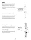
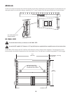
Correct use of all suspension hardware and components is imperative in sound system rigging and deployment.•
Always calculate suspended loads before lifting to ensure suspension components and hardware are used within their respective load limits.•
Research local codes and regulations to fully understand the requirements for suspended loads in the venue in which the equipment is to •
be suspended.
Use only shackle holes for suspension of array.•
Be absolutely certain of the integrity of any structural member intended to support suspended loads. Hidden structural members can have hidden •
structural weakness.
Consult a professional mechanical or structural engineer licensed in the jurisdiction of the sound system installation to review, verify, and approve •
all attachments to the building or structure.
Never assume anything• —owner or third-party supplied suspension attachment points may not be adequate for the loads to be suspended.
Employ the services of a professional rigger for hoisting, positioning, and attaching the equipment to the supporting structure.•
Always inspect all components (enclosures, suspension brackets, pins, frames, bolts, nuts, slings, shackles, etc.) for cracks, wear, deformation, •
corrosion, missing, loose, or damaged parts that could reduce the strength of the assembly before lifting. Discard any worn, defective, or suspect
parts and replace them with new appropriately load-rated parts.
Shock Loading
When a load is either moved or stopped, its static weight is magnified. Sudden movements can magnify the static weight several times. This
magnification of static weight is termed “shock loading”. Shock loading poses a danger to equipment and workers. The effects of shock loading can
be instantaneous, or they may remain undetected unless the equipment is visually damaged. Avoiding shock loading requires careful planning and
knowledge of equipment, rigging, and lifting practices.
Shock loading of equipment and structures is usually confined to lifting and installation, but natural forces (winds, earthquakes) can impose shock
loads several times the static load. This is why structures and suspension equipment must be capable of supporting several times the weight of the
equipment suspended.
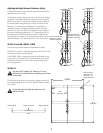
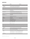
WideLine-10 Working Load Limits and Design Factors
The following chart (Table 2) provides Working Load Limit data at various Design Factors. The tabulated Design Factors are for static loads only. The
choice of which Design Factor to use will depend upon the jurisdiction and venue of installation, as well as the conditions of suspension. Dynamic
conditions are determined by unknown, installation-specific factors and should be referred to a Licensed Structural Engineer for clarification before
proceeding with any suspension of the equipment. The data presented is based upon the listed component weights:
Table 2
Component Weight 4:1 Design Factor 5:1 Design Factor 7:1 Design Factor 10:1 Design Factor
WL2102 70 lb / 31.8 kg 2300 lb / 1040 kg 1800 lb / 836 kg 1300 lb / 597 kg 920 lb / 418 kg
WL2102-w 83 lb / 37.7 kg 2500 lb / 1130 kg 2000 lb / 909 kg 1400 lb / 649 kg 1000 lb / 455 kg
AF2102-LA 37 lb / 16.8 kg – – 1423 lb / 646.8 kg 996 lb / 452.7 kg
WL SMALL GRID 33 lb / 15.0kg 1800 lb / 794 kg 1400 lb / 636 kg 1000 lb / 455 kg 700 lb / 318 kg