


5
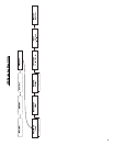
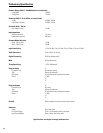
Audio Inputs
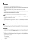
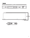
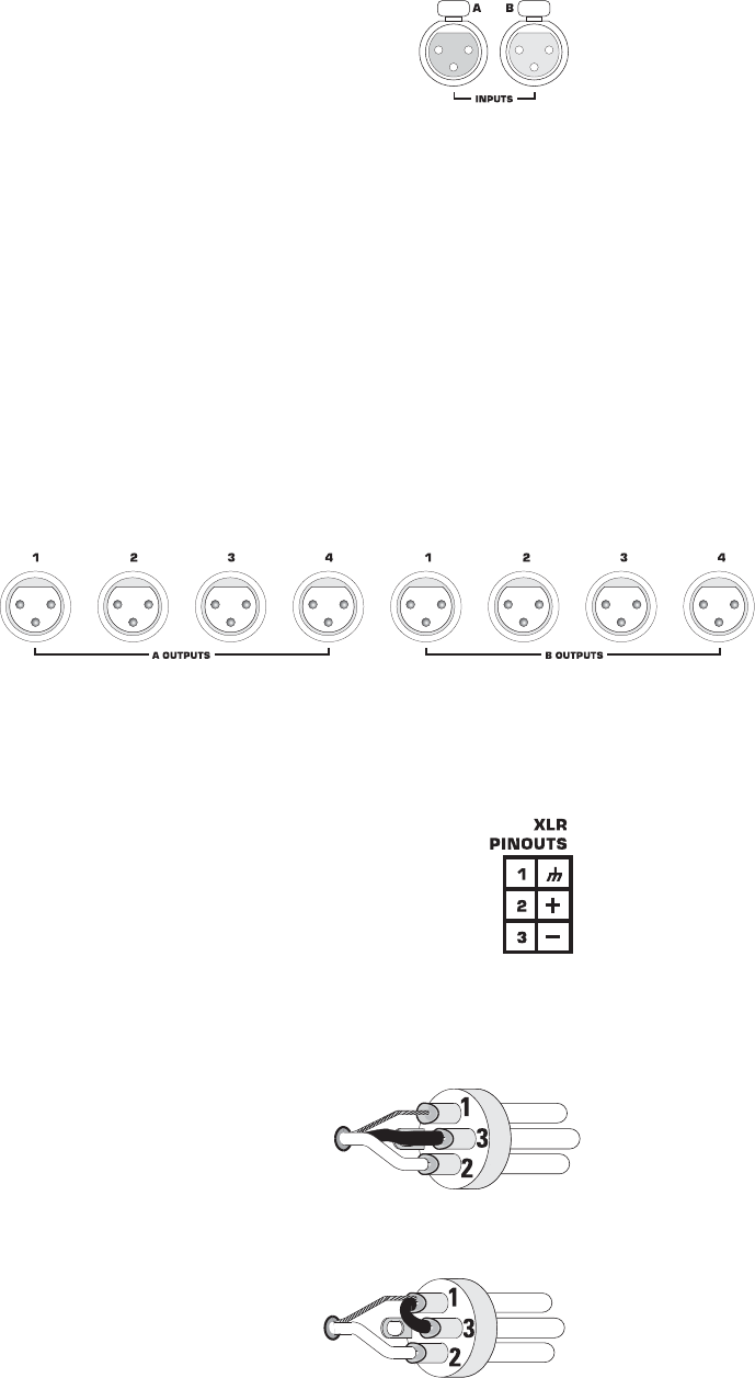
On the rear panel, there are two female XLR line-level inputs marked INPUTS below
the connectors and designated A and B above the connectors. Connect the line-level
analog audio inputs to these connectors. Input sensitivity can be selected from the
Setup Menu; selections are 1.5 V
rms
/6 dBu, 3 V
rms
/12 dBu, 9 V
rms/
21 dBu, or 18 V
rms
/
27 dBu. These values correspond to the maximum input signal level that can be
applied to the inputs without clipping. The signal's source impedance should be less
than 600 ohms.
We recommend balanced connections be used. Balanced connections will reduce AC
hum and interference, especially with long cable runs. Unbalanced connections may
be suitable for short cables. The input impedance is 11k ohm for balanced connections
or 69k ohm for unbalanced connections.
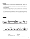
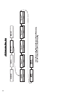
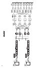
Audio Outputs
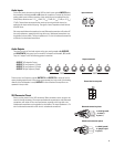
There are two sets of line-level outputs on the rear panel grouped as A OUTPUTS
and B OUTPUTS. Each group has four male XLR connectors numbered 1, 2, 3, and 4.
They are “mapped” with the following general convention:
OUTPUT 1- Subwoofer Output
OUTPUT 2- Low Frequency 1 Output
OUTPUT 3- Low Frequency 2 Output
OUTPUT 4- High Frequency Output
There are two Low Frequency outputs (OUTPUT 2 and OUTPUT 3) to allow for low fre-
quency shading requirements of line arrays when operated in triamp mode. If the shading
network of the loudspeaker is used, OUTPUT 2 is not utilized and the amplifiers are
operated in biamp mode.
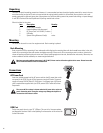
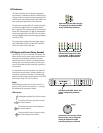
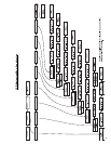
XLR Connector Pinout
Shown are the pinouts for the XLR connectors. Male connectors shown, pinout is the
same for female connectors. We recommend balanced connections be used. Balanced
connections will reduce AC hum and interference, especially with long cable runs.
Unbalanced connections may be suitable for short cables. The input impedance is 11k
ohm for balanced connections or 69k ohm for unbalanced connections.
1= shield (ground)
3= jumper to pin 1
2= plus (+)
1= shield (ground)
3= minus (-)
2= plus (+)
Balanced connection pinout
Unbalanced connection pinout
Output connectors
Input connectors
Pinout label on rear panel