


23
EXAMPLE
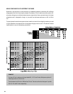
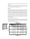
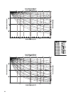
A loudspeaker (sensitivity: 94 dB @ 1W, 1 meter) in a busy office covers an area with an ambient noise
of 72 dBA, measured at a seated person’s ear position at the desks. The client wants superb
intelligibility, so your goal is to provide an SPL of 97 dB (72 plus 25) to the intended listeners. The ceiling-
mounted speaker is about 6 feet, or 1.8 meters, above the listeners’ ears. The dB figure from the inverse
square law conversion guide for that distance is 5.2 dB; this means that the loudspeaker would have
to produce 102.2 dB (97 plus 5.2) at a distance of 1 meter to achieve 97 dB at a distance of 1.8 meters.
The loudspeaker will require a power level 8.2 dB (102.2 minus 94) greater than 1 watt; this works out
to 6.6 watts. The speaker transformer taps are 0.5, 1, 2, 4, and 8 watts; the closest choice would be
the 8-watt tap, which turns out to be only 0.8 dB higher than the design ideal.
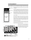
SELECTING THE AMPLIFIER
After you’ve determined the power taps for each loudspeaker transformer, add them up. The sum will be what
you determine your amplifier requirements from. If you have 16 loudspeakers tapped at 2 watts, seven at 1 watt,
and eight at 10 watts, the total audio power the loudspeakers want is 119 watts.
Thanks to a transformer phenomenon called insertion loss, though, your amplifier needs to provide more power
than the loudspeakers will draw. High-quality speaker transformers typically have an insertion loss of about 1 dB,
meaning that it takes about 1.25 watt going into the transformer to put 1 watt into the loudspeaker. A lower-
quality transformer may have a loss of 2 dB, which requires approximately 1.6 watts for every watt that the
loudspeaker receives. Poor-quality transformers may have even higher losses, but they will probably degrade
the system’s audio performance severely even if there is adequate amplifier power to overcome the losses.
To compensate for the insertion loss, add a corresponding percentage to the sum of the transformer power taps.
For transformers with a 1 dB loss, add about 25%; in the example above, that would increase 119 watts up to
149 watts.
Next, it is a good engineering practice to add another 25% to the figure. This allows a margin both for dynamic
audio headroom and for some future adjustments to the system—an added speaker or two, a few transformer
tap changes, etc. That would bring the total power requirement for the example system up to 186 watts. This
would be the
minimum
power rating for the amplifier you choose.
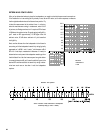
INSTALLATION TIP:
Once the sound system is installed and operational, turn the amplifier off and take an impedance
measurement across the distributed line at the amplifier output, using an audio impedance meter
(
not
an ohmmeter). Record the measurement for later use. If you ever have to make a service call
on the system, measure the impedance again and see how it compares to the recorded figure; it’s
a quick and easy way to see if anything in the distributed line system has been changed. Likewise,
measure the impedance anytime you’ve changed a transformer tap, added or removed a loud-
speaker, or made any other adjustment to anything on the distributed line.