


11
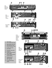
The standard input panel installed on the CX Series amplifier has balanced Euro-style detachable header inputs,
gain controls, and the Parallel-Stereo-Bridge switch. The panel’s circuit board has solder footprints for passive
roll-off circuit components, input isolation transformers, and other special customizations.
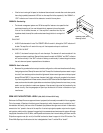
The MX-1 Input Expander panel may be installed in the upper panel position. It features XLR inputs and 1/4" RTS
inputs. Installation instructions are included with the expansion kit.
Other available accessories include a universal filter and a stereo power limiter; more are in development. Contact
QSC for more details before using accessories with CX amplifiers. See the CX Application Notes also.
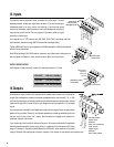
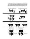
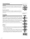
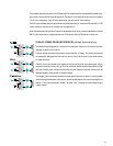
PARALLEL, STEREO, OR BRIDGED OPERATION (CX6, CX6T, CX12 and CX12T only)
The Parallel-Stereo-Bridge switch is located on the input panel. Always turn off the amplifier before
changing the position of this switch.
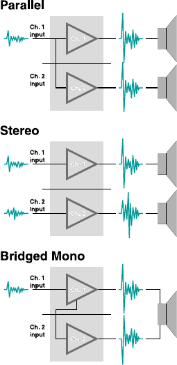
The most commonly used operating mode for a power amplifier is “Stereo,” in which the two channels
are independent and separate all the way from input to output. Set the switch in the center position
for stereo operation.
“Parallel” ties the two channel inputs together so that both will be driven by the same signal, without
the need for external jumpers or wiring. After the inputs both channels operate independently; though
they carry the same signal, their gain controls affect only their respective channels, and they must use
separate speakers. Never parallel the speaker outputs!
The “Bridge” position uses both channels to provide about three times the power to a single speaker
load that a single channel does. In this position, the switch feeds channel 2 with an inverted signal from
channel 1. Thus, when one channel “pushes,” the other “pulls,” providing twice the voltage swing of
a single channel.