


EN
8
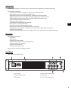
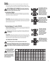
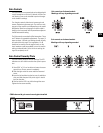
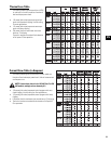
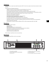
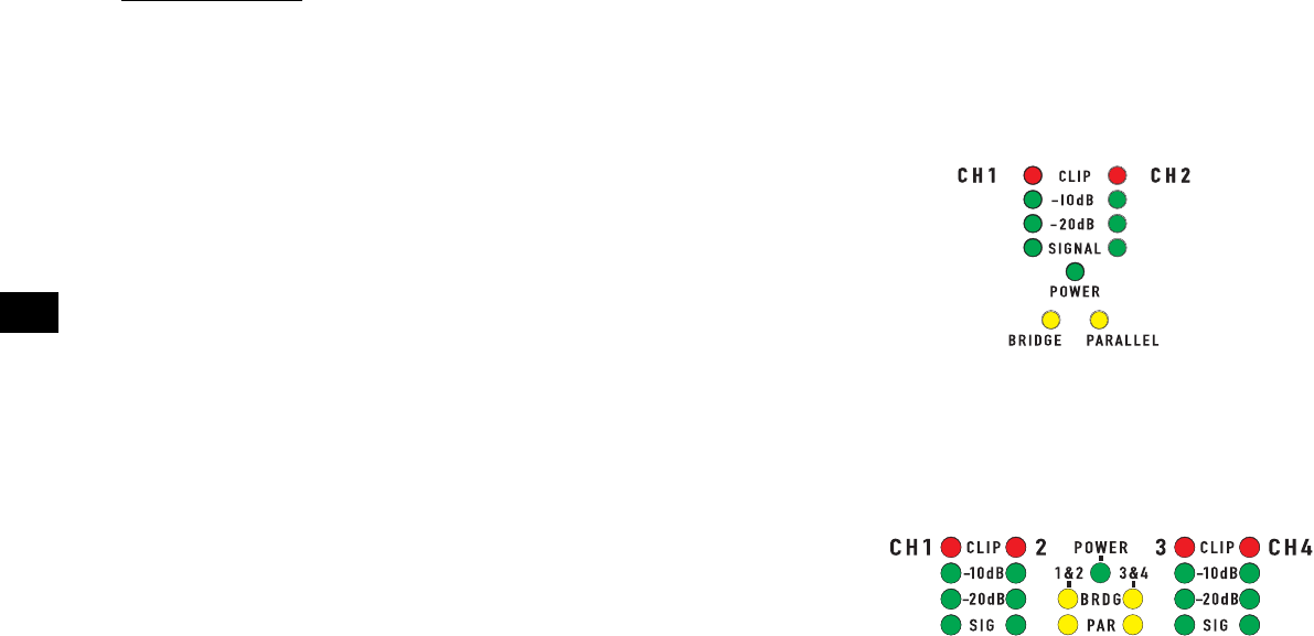
LED Indicators
The LED indicators can be used to monitor system operation and identify common prob-
lems.
POWER: GREEN, above the BRIDGE (BRDG) and PARALLEL (PAR) indicators.
Normal indication: AC switch ON: LED will illuminate.
If no indication: Check AC power cord and AC outlet. Confirm that DataPort 1-2 is
not holding the amp in 'Standby' mode.
CLIP: RED, adjacent the channel number markings.
Normal indication: illuminates whenever the amplifier is driven beyond full power.
The resulting distortion corresponds to the brightness of the LED. Distortion that
causes only brief flashing may not be audible.
-During muting, the LED fully illuminates. This occurs during normal "On-Off" muting.
Abnormal indication:
-Bright red illumination while the amp is being used indicates either thermal muting
or a shorted output.
-If the amplifier overheats, the fan will run at full speed, and operation should resume
within one minute. Allow the fan to run, and make sure the amplifier ventilation is
adequate.
-A shorted or overloaded output circuit will cause excessive Clip flashing and possible
overheating.
If distortion is audible without a Clip indication, the problem is either before or after
the amplifier. Check for damaged speakers or overloaded signal source. The amplifier
Gain control should be in the upper half of its range to prevent input overload.
SIGNAL, -20dB, -10dB: GREEN, under each Clip LED.
Normal indication: The SIGNAL indicator illuminates when the input signal exceeds
-35 dB, the -20dB indicator illuminates when the signal exceeds -20dB, and the -10dB
indicator illuminates when the signal exceeds -10dB.
If no indication: check Gain settings and increase gain if necessary. Check input con-
nections and audio source for signal. If the Clip LED illuminates with little or no Signal
indication, check the output wiring for shorts.
Abnormal indication: If the SIGNAL (SIG), -20dB, or -10dB LED illuminates with no
signal input, there may be system oscillations or some other malfunction. Disconnect
the load and fully reduce the gain. If the LED remains on, the amp may need servicing.
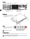
BRDG and PAR:
Each channel pair has a YELLOW LED for Bridge Mode, and an ORANGE LED for Paral-
lel mode. These show how the rear panel switches are set (see Setting the Mode
Switches). In Stereo mode, both LEDs should be OFF.
LED indicators on 2-channel models.
LED indicators on 4-channel models.