


EN
7
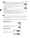
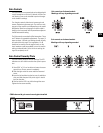
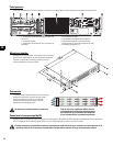
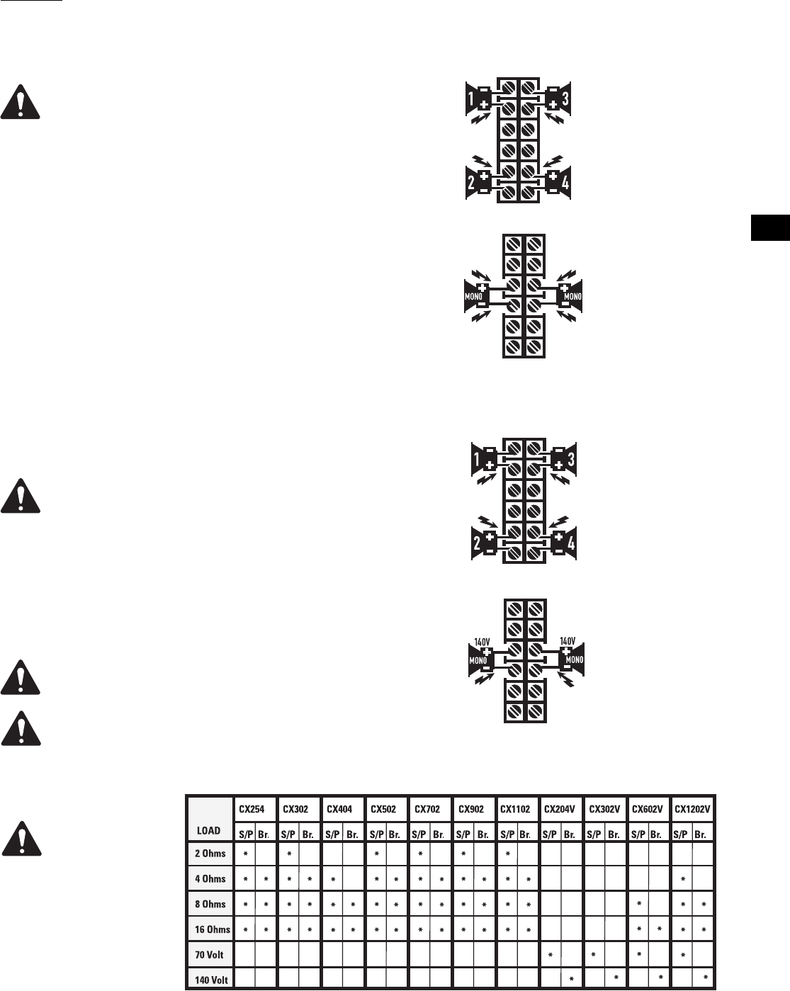
70V stereo or parallel
connection- Each 70V
zone connects to its
respective channel.
Ensure that all speaker
connections maintain
proper polarity.
140V Bridge connection-
Wire each bridged pair to
a 140V circuit as shown.
Check for proper polarity.
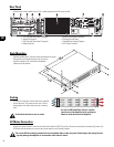
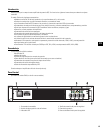
Outputs
Wiring connections are shown on the back of the chassis. Carefully note the
polarity marks, which are arranged to make Bridge Mode connections easier.
Four-channel models are shown in the examples; two-channel models are similar.
OUTPUT TERMINAL SAFETY WARNING! Do not touch output termi-
nals while amplifier power is on. Make all connections with ampli-
fier turned off. Risk of hazardous energy!
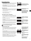
Low Impedance Outputs
Stereo and Parallel Mode- Connect each loudspeaker to its own channel of
the amplifier, as shown on the chassis label. The mode configuration switches
must be set for Stereo or Parallel mode.
Bridge Mode- Bridge mode configures the channel pair to drive a single high-
power loudspeaker load. The mode configuration switches must be set for Bridge
mode. Use only the first channel's input and Gain control. Set the second chan-
nel's Gain control at minimum.
Distributed Outputs (“V” models, 70V/140V)
Stereo and Parallel Mode- Connect each 70V circuit to its own channel of the
amplifier, as shown on the chassis label. The mode configuration switches must
be set for Stereo or Parallel mode.
70V Output- Risk of hazardous energy! Class 2 wiring shall be used
for 70V outputs.
Bridge Mode- Bridge mode configures the channel pair to drive a single 140V
audio circuit. The mode configuration switches must be set for Bridge mode. Use
only the first channel's input and Gain control. Set the second channel's Gain
control at minimum. Connect the load as shown on the chassis label.
140V BRIDGE MODE PRECAUTIONS:
Class 3 Wiring shall be used for bridged mono 140V outputs.
Connect only 140V distributed audio circuits in bridged mode. Do not
use 70V loads in bridge mode! Use Stereo or Parallel mode channels
to drive 70V loads. 140V is the minimum for bridge mode operation.
Low Impedance Stereo or
Parallel Connection- Each
loudspeaker load con-
nects to its respective
channel. Four channel
model shown. Ensure that
all speaker connections
maintain proper polarity.
Low Impedance Bridge
Connection- Each loud-
speaker load connects to a
bridged channel pair. Four-
channel model shown.
Check for proper polarity.
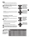
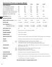
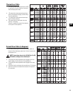
Loads Rated by Model
Be sure the model
amplifier you are using
is rated for the load!
An asterisk (*)indicates the
model is rated for the load.
(S/P)= Stereo/Parallel mode
(Br.)= Bridge mode