


15
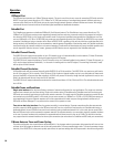
RS-232
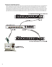
The RS-232 is an optional utility serial port for accessing advanced features. Connect to an
available COM port on your PC and communicate using a terminal control program such as
Windows Hyperterminal.
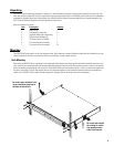
Use a normal serial data cable with a DB-9 male plug to connect to the BASIS 914lz. To con-
nect the cable, orient the connector properly, then push into the receptacle until it is firmly
seated; tighten the retaining screws “finger tight”. Communications should be 9600 baud,
no parity, 8 data bits, 1 stop bit, and flow control Xon/Xoff.
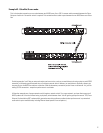
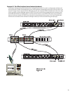
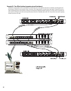
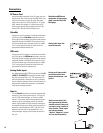
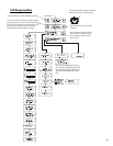
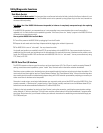
Ports
PORT A through PORT H are QSC DataPorts. When using the
BASIS 914lz with QSC DataPort-equipped amplifiers or QSC
DSP products (DSP-3, DSP-4) connect to the BASIS 914lz using
QSC DataPort cables. The 914lz supports up to sixteen channels
of DataPort audio and amplifier status monitoring. This can be
eight 2-channel amplifiers or two 8-channel amplifier or other
suitable combinations. If connecting a multi-DataPort amplifier,
be sure to connect the DataPorts sequentially (i.e. Amp DataPort 1 to BASIS DataPort A,
Amp DataPort 2 to BASIS DataPort B, and so on). This practice assures proper amplifier
reporting in QSControl.net.
To connect the cable, orient the connector properly, then push into the receptacle until it is
firmly seated; tighten the retaining screws “finger tight”.
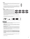
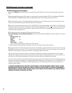
LED Indicators
When the BASIS 914lz is plugged into a properly functioning AC outlet, it will power up and
briefly display a welcome screen on the LCD display.
POWER Indicator- This blue indicator illuminates when the BASIS 914lz is plugged into a
properly functioning AC source. There is no power switch on the BASIS 914lz. This helps to
prevent accidental system shutdowns.
DIAGNOSTIC Indicator- This red diagnostic LED reports several possible operational con-
ditions. During boot-up, it is used to continually blink a “dot-dash” pattern if the power-on
memory self-test fails. During normal operation, if any non-recoverable system fault occurs,
the diagnostic indicator will remain on, requiring a power restart. If this condition persists,
contact QSC’s Technical Services for assistance.
The diagnostic LED is also used to indicate an update is in progress during a remote firm-
ware update cycle. First, the LED will blink slowly, indicating the memory erase cycle, then it
will blink rapidly, indicating the memory write cycle. NOTE! During a firmware update, it
is critical the unit remain powered on for the entire process in order to complete
successfully.
The diagnostic LED may also be controlled by using the QSControl.net software. This fea-
ture is particularly helpful for identifying a particular unit.
(continued, next page)