


15
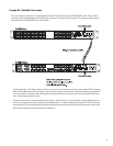
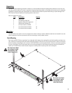
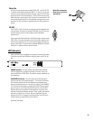
Relay Out
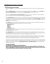
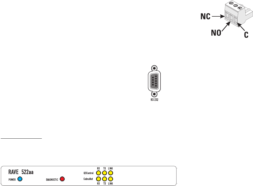
Two sets of relay contacts are provided, RELAY OUT 1 and RELAY OUT
2. Contacts are floating and rated for 30VDC, 1A. There is one common
terminal, one normally-closed contact terminal and one normally-open
contact terminal. These are labeled as C, NC and NO on the rear panel.
When the relay is not energized, the C terminal is connected to the NC
terminal and the NO terminal is not connected; when the relay is ener-
gized the C to NC connection is opened and the C to NO connection is
closed.
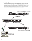
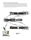
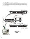
RS-232
The RS-232 is a utility serial port for accessing certain diagnostic fea-
tures and setup. Connect to an available COM port on your PC and com-
municate using a terminal control program such as Windows
Hyperterminal.
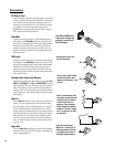
Use a normal serial data cable with a DB-9 male plug to connect to the
RAVE 522aa. To connect the cable, orient the connector properly, then
push into the receptacle until it is firmly seated; tighten the retaining
screws “finger tight”. Communications should be 9600 baud, no parity,
8 data bits, 1 stop bit, and flow control Xon/Xoff.
LED Indicators
When the RAVE 522aa is plugged into a properly functioning AC outlet,
it will power up and briefly display a welcome screen on the LCD dis-
play.
POWER Indicator- This blue indicator illuminates when the RAVE
522aa is plugged into a properly functioning AC source. There is no
power switch on the RAVE 522aa. This helps to prevent accidental sys-
tem shutdowns.
DIAGNOSTIC Indicator- This red indicator illuminates during the
power-on self test, then should extinguish. If it remains illuminated,
this indicates that the self-test has detected an unexpected event,
such as corrupted firmware or a memory boot failure. If the DIAGNOS-
TIC LED remains illuminated, try resetting the RAVE 522aa by cycling
power off and on once. Should the indication persist, contact QSC’s
Technical Services for guidance. During operation, any system fault
will fully illuminate the indicator. During a “flash” update, the indicator
will blink on and off; this is normal. Any error detected will be dis-
played on the LCD. For purpose of unit identification, the LED can be
remotely turned on using QSControl.net software.
(continued, next page)
Relay Out connections.
Refer to text, at left, for
explanation.