


14
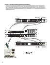
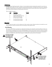
Connections
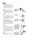
AC Power Cord
Insert the molded receptacle of the AC power cord into the
AC power inlet on the back of the RAVE 522aa. Plug the AC
line connector into the AC outlet. The power supply will
accept from 100 to 240 Volts AC, 47 to 440 Hertz, without
any changes. If a different type of IEC power cord is
required than the one supplied with your 522aa, contact
QSC’s Technical Services Department.
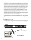
CobraNet
Connect one end of a category-5 cable terminated with a
RJ45 plug into the CobraNet receptacle. Insert the RJ45
plug into the receptacle with the lock-tab oriented toward
the bottom of the RAVE 522aa and push firmly until the
connector locks into place (usually an audible “click” can
be heard). Connect the other end to the appropriate Cobra-
Net network port.
QSControl
Connect one end of a category-5 cable terminated with an
RJ45 plug into the QSControl receptacle. Insert the RJ45
plug into the receptacle with the lock-tab oriented toward
the bottom of the RAVE 522aa and push firmly until the
connector locks into place (usually an audible “click” can
be heard). Connect the other end to the appropriate QSCon-
trol.net network port.
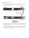
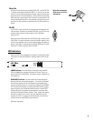
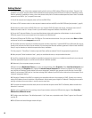
Analog Audio Inputs and Outputs
Eight balanced audio inputs and outputs are provided, CH 1
INPUT - CH 8 INPUT and CH 1 - CH 8 OUTPUT. Plug the
input signal terminal block connectors into the input recep-
tacles. Connection pin-out is printed on the rear label for
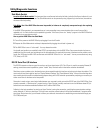
reference. Refer to the illustrations for balanced and unbal-
anced connections. Use balanced audio connections when-
ever possible.
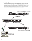
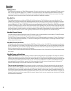
Omni In
The six Omni In connectors are two-pin terminal block con-
nectors. They can accept contact closure devices (switch,
relay contacts) or 10k ohm variable resistors. The contact
closure and logic devices accommodate on/off or state-
change events; the variable resistor input provides full 8-bit
resolution allowing for incremental-change events. Refer to
the illustrations for connection recommendations. NOTE!
+48 volts is the absolute maximum that can be applied to
the + pin without damage. Voltage is with respect to chas-
sis or the - pin.
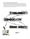
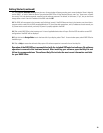
Logic Out
The four Logic Out connectors are two-pin terminal block
connectors. They provide CMOS logic level compatible sig-
nals for external devices.
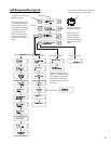
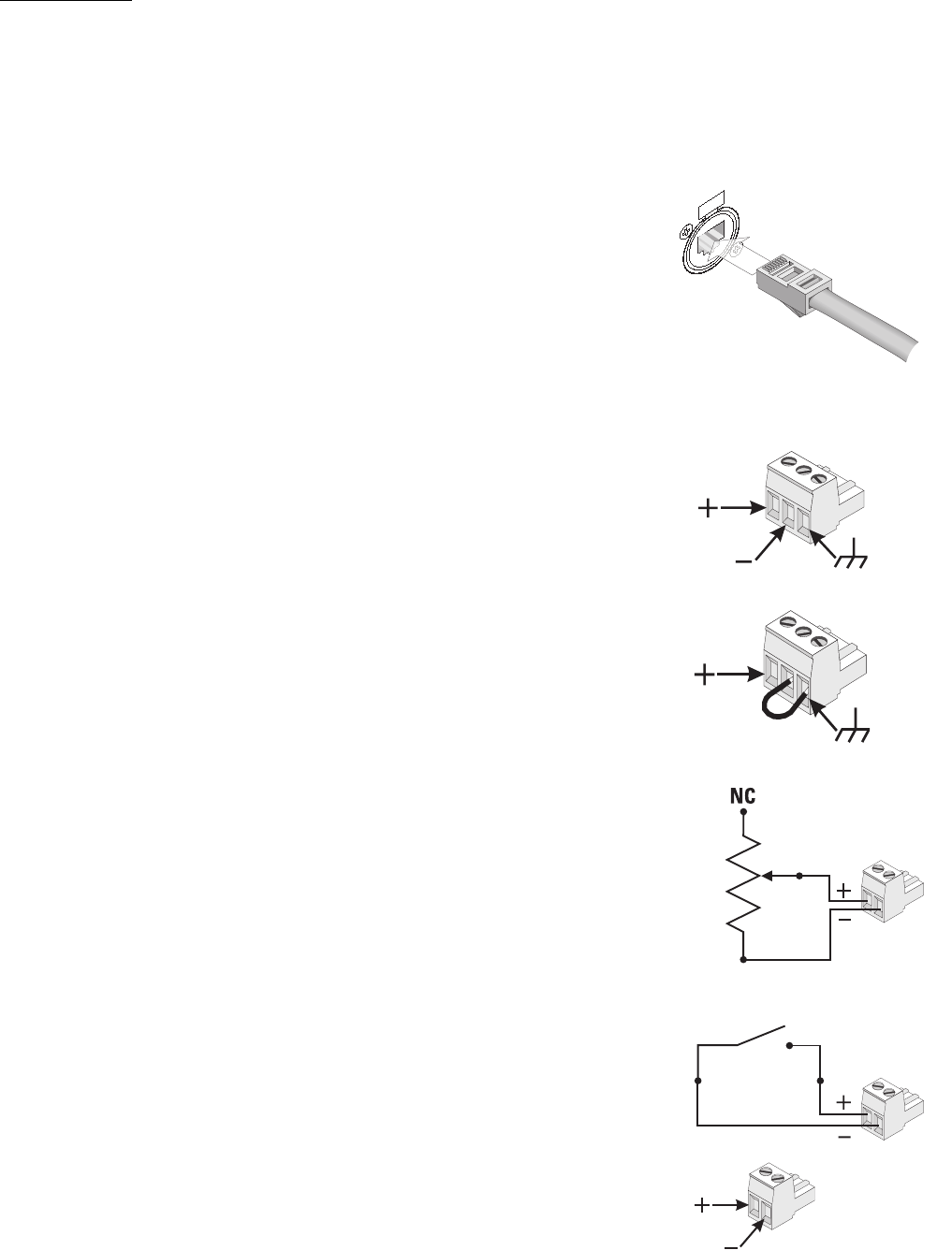
Analog audio input- bal-
anced connection.
Logic Out connections.
Negative (-) terminal is at
chassis potential. Positive
(+) terminal logic level is
switched using software.
CobraNet and QSControl
connection. Accepts rug-
gedized or normal shell-
less RJ45 plugs.
Omni In connections. Vari-
able input must be 10k ohm
variable resistor. Contact
closure input can be a
switch or relay contacts.
These inputs can operate
software “devices”. Nega-
tive (-) terminal is at chas-
sis potential.
Analog audio input- unbal-
anced connection. Note
jumper wire between - and
ground.