


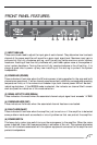


(14) LOW CUT SWITCH
This switch is used to activate the LOW CUT filter for the corresponding channel. It is again a push-push
type switch, requiring a small "tool" to activate. The IN position routes the input signals through the 40
Hz LOW CUT filter, while the OUT position bypasses the filter. This filter will cut extremely low
frequencies, protecting speakers from the possibility of over-excursion. The filter low-frequency roll off is
12 dB per octave. The LOW CUT filter for each channel will function independently of the crossover
function to be discussed next.
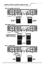
(15) CROSSOVER SWITCH (150 Hz X OVER)
This switch is used to activate the 150 Hz crossover for the corresponding channel. It is also a
push-push type switch and requires a small "tool" to activate. The offers two 150 Hz crossovers. These
are specially designed features that enhance the response of most loudspeakers in a typical bi-amped
application. Rather than just having a fiat output curve, these crossovers use special filters to tailor the
response and provide a flat acoustical output. This type of crossover "sounds" more natural than
conventional "state-variable" type crossovers.
With the switch IN, the input signals are routed through the crossover, and the low frequencies are
automatically sent to the corresponding channel. At the same time, the high frequencies are sent to
the HIGH OUT (17) jack and must then be patched to INPUT of the other channel of this amplifier or to
another amplifier input to complete the bi-amped system. Additionally, the low frequencies are sent to
the THRU/LOW OUT (16) jack, and can be patched to other amplifier inputs to permit even larger
systems. With the switch OUT the crossover is defeated, and input signal is routed directly to the
respective power amp channel. The crossover frequency is fixed at 150 Hz and cannot be changed. The
crossover configuration is a 4-pole Linkwitz-Riley approximation.
(16) THRU/LOW OUT JACKS
As per previous crossover discussion, this 1/4" jack supplies low-frequency out signals from the
activated crossover for patching to additional power amplifier inputs, providing added flexibility in larger
bi-amped systems. When the crossover function is not activated, this jack converts to a THRU function,
where the output of the electronically balanced input circuitry is supplied to this jack. The THRU function
provides the means to patch a full range input signal to the other input of this amplifier (parallel
mode), or to other amp inputs in the same rack. This function allows one balanced mixer feed to be
connected to the amp via the desired balanced input connector (XLR, 1/4", Barrier), and then further
distributed locally. Regardless of the crossover switch position, this 1/4" jack provides an unbalanced
(tips/sleeve) output to be patched with single conductor shielded cables.
(17) HIGH OUT JACKS
Again, as per previous crossover discussion, this 1/4" jack supplies high frequency out signals from the
activated crossover for patching to this amplifier and/or additional power amplifier inputs. Unlike the
low-frequency crossover output, that is automatically routed to the associated channel, the high-frequency
output signal must be patched to some suitable input in order to complete the bi-amped system. This
1/4" jack also provides an unbalanced (tip/sleeve) output to be patched with signle-conductor shielded
cables.
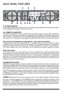
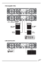
INDUSTRIAL AND COMMERCIAL INSTALLATIONS
For commercial and other installation where sustained high-power operation is required, the amplifiers
should be mounted in a standard 19" rack. It is not necessary to leave a rack space between each
amplifier in the stack since each fan pulls air in from the rear and exhausts the hot air our the front.
However, an adequate cool air supply must be provided for the amplifier when rack mounted. The
internal fan must have a source of air that is not preheated by other equipment. The amplifier will start up
in low speed fan operation and will normally stay at low speed unless sustained high-power operation