


6
(9) SPEAKON OUTPUTS
The amplifiers utilize three 4-conductor Speakon connectors, one for each channel and one for BRIDGE
mode. Please refer to the BRIDGE MODE section of this manual before attempting to use this mode.
For each channel Speakon, the same impedance rules apply as with the binding posts. Internally, all the
Speakons are wired in what is called the “high current” mode with pins 1+ and 2+ in parallel, and pins 1-
and 2- in parallel. For the CHANNEL A and CHANNEL B Speakons, the respective channel output
appears on pins 1+ and 2+. Pins 1- and 2- are chassis ground. For the BRIDGE Speakon. CHANNEL A
appears on pins 1+ and 2+, and CHANNEL B appears on pins 1- and 2-. Always check the Speakon
connector wiring carefully before using.
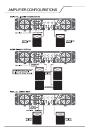
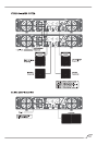
(10) MODE SWITCH
This switch is used to select STEREO or BRIDGE mode operation. It is a conventional push-push type,
requiring a small “tool” to activate. The IN position is BRIDGE mode, the OUT position is STEREO mode.
Exercise care when selecting the BRIDGE mode. Accidental selection of this mode could damage
loudspeakers, particularly in bi-amped systems. Amplifier BRIDGE mode theory will be covered later
in this manual.
(11) GROUND LIFT SWITCH
Avoid background noise and hum.
Turn switch right or left to cut electrical noise.
Always turn power off before using this feature.
(12) FAN GRILL
Two 2-speed DC fans supplies cool air to the amplifier. THIS INTAKE SHOULD NEVER BE BLOCKED!
The fans switches to high speed automatically when the unit requires additional cooling. At idle and cool,
the fans should be in low speed. The fans should never stop unless the amplifier is switched off or the
AC mains power source is interrupted.
(13) COMBO INPUT CONNECTOR
The combo connector offers both female XLR and 1/4" phone jack balanced inputs for each channel.
The XLR is wired with pin 1 as ground, pin 2 positive input, and pin 3 negative input. The 1/4" phone jack
is a tip/ring/sleeve (3-conductor) type, with the tip being positive input, the ring negative input, and the
sleeve ground. It is important to realize that the XLR 1/4" jack, and barrier strip inputs are all in parallel,
therefore a balanced input to the associated channel can be accomplished using a male XLR, a
3-conductor phone jack, or bare wires connected to the barrier strip.
As an alternative, the 1/4" input can also be used with a regular tip/sleeve (2-conductor) type plug
commonly found on single-conductor shielded patch cord. In this case, the input becomes unbalanced
with the tip as positive input, and the sleeve ground (the ring being grounded by the sleeve of the plug).
An additional unique feature of this 1/4" input jack is something called a "quasi-balanced" input. The
sleeve of this jack is connected to chassis ground through a relatively low-value resistance that is part of
a ground loop elimination circuit. This circuitry will provide hum-free operation when relatively short 1/4"
cable patches are made to this input from various outputs on this amplifier, or from other equipment that
shares the same rack with this amplifier. The quasi-balanced circuitry is "automatic" and virtually
"invisible" in normal usage. This feature can be defeated with a jumper on the barrier strip from the
input terminal of that channel to the ground terminal.