


10
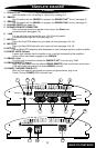
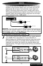
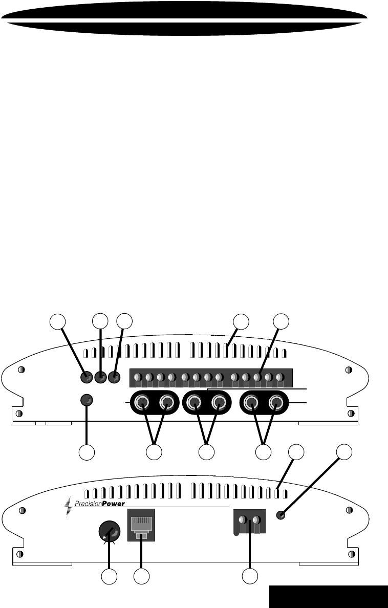
ENDPLATE DIAGRAM
Pro6800
-
+
POWER / MUTE
Designed and Handcrafted in the U.S.A.
QBASS
0
+18
QBASS
REMOTE
PC PRO 650 12/13/96
13
11
12
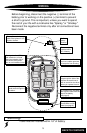
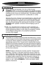
1. Q SELECT 4/2
Push this button in for a Q setting of 4 and out for a setting of 2.
2.
Q
BASS
1
Use this switch with the
Q
BASS
2 to program the
Q
BASS PLUS
™
circuit. (see page 2).
3.
Q
BASS
2
Use this switch with the
Q
BASS
1 to program the
Q
BASS PLUS
™
circuit. (see page 2).
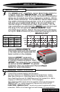
4. COOLING VENTS (see page 16).
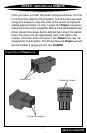
5. SPEAKER/REMOTE CONNECTOR
After connecting remote and speaker wires, plug in the
PowerLock
connectors here (see pages 7-9).
6. -12dB
For use with high level inputs (4V up to 12V). Push this switch
in to attenuate the input by 12dB (see page 14).
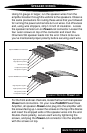
7. INPUTS A
Plug in the Front RCA leads from your head unit here (see page 14 & 16).
8. INPUTS B
Plug in the Rear RCA leads from your head unit here (see page 14 & 16).
9. OUTPUTS
Left and Right RCA outputs provide band pass or mono low pass signal to another amplifier.
10. POWER / MUTE indicator
A green light indicates that the amplifier is on, a red light indicates that the amplifier's
muting circuits have been engaged by an
ACM-420
.
11.
Q
BASS
™
Level
Turn this control clockwise to boost the
Q
BASS PLUS
™
circuit by up to 18dB.
12.
Q
BASS REMOTE
™ plug in
Plug in the data cable from the optional
Q
BASS REMOTE
™
dash mount level control here.
(This will bypass the amplifier's on board
Q
BASS
™
control)
13. POWER / GROUND
POWERLOCK
After you have securely connected your power and ground wires, plug in the
Power / Ground
POWERLOCK
connector here.
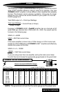
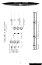
CHANNEL 5 / 6
L- L+ REM R+ R-
CHANNELS 3 / 4
L- L+ R+ R-
OUTPUTS
INPUTS B
L R
-12dB
CHANNELS 1 / 2
L- L+ R+ R-
L RL R
INPUTS
A
Q
BASS
2
1
Q SELECT 4/2
1
2
3
54
7 8 9
4
10
6
BACK TO CONTENTS