


1312
ADJUSTING THE POWERED
SUBWOOFER
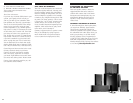
The specially finished PSW650 Powered
Subwoofer included in your RM7500 System
features two 10-inch direct radiating
drivers, 250-watt power amplifier, and
dual Power Port bass ports. It offers a
wide range of setting options. To perfectly
optimize this subwoofer we recommend
the following settings as starting points,
but the option that is best for you depends
on your electronics, main speakers and per-
sonal taste. After you have become familiar
with what the settings do, experiment with
alternate options to find the method that
works best for your system.
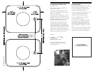
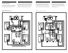
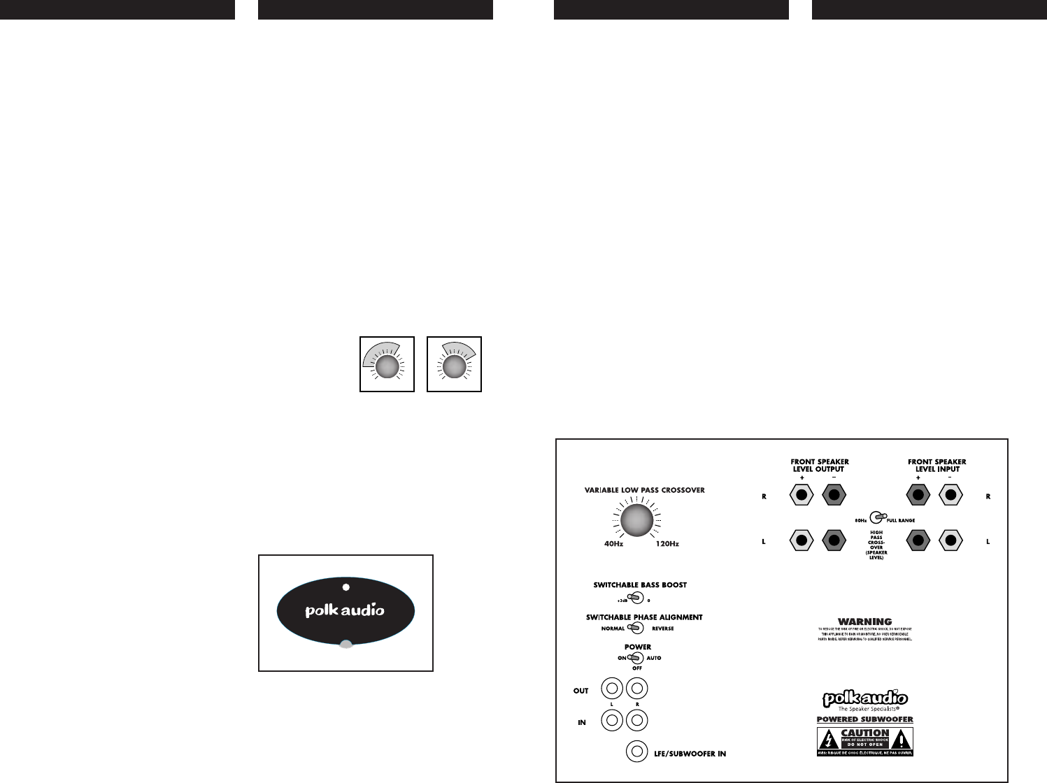
SUBWOOFER SETTINGS (Figure 9)
On the back of the subwoofer, you will see
the following controls:
• Variable Low Pass Crossover Control
• +3dB Switchable Bass Boost Switch
(to boost output of low output subwoofer
output jacks)
• High Pass Crossover Toggle
The “80 Hz” setting provides extra bass
filtering for front satellites. The “Full Range”
setting provides best performance in most
cases.
• Switchable Phase Alignment Toggle
• The Subwoofer Volume Control
is found under the logo pod on the
front of the subwoofer.
These controls allow you to optimize perfor-
mance of the powered subwoofer to match
your audio system, room acoustics, and
program material.
VARIABLE LOW PASS CROSSOVER (Figure 9)
This control adjusts the frequency range over
which the subwoofer operates. It only affects
signals that are sent through the line level,
subwoofer and speaker level inputs. It has
no effect on signals fed into the LFE input.
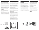
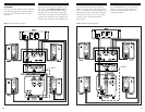
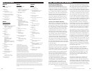
RECOMMENDED CROSSOVER SETTINGS —
ON WALL & OFF WALL
Mounting your right and left front satellites
on the wall tends to increase their bass.
Mounting them on stands away from the
sides of the room tends to decrease their
bass. If you mount the satellites on the
wall, we recommend setting your variable
crossover control at a lower setting.
(Figure 10) If you mount the satellites on
stands, we recommend setting your variable
crossover control at a higher setting.
(Figure 11)
Generally, turning the knob “up” (clockwise)
will add more “warmth” to the bass and
lower midrange, possibly at the sacrifice
of bass “tightness” and midrange clarity.
Conversely, turning the knob “down” (counter
clockwise) will make the bass and lower
midrange sound “thinner.”
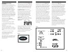
SUBWOOFER LEVEL CONTROL (Figure 9a)
Subwoofer level is adjusted via the knob
on the front of the subwoofer under the logo
pod. Play a piece of music that has an aver-
age amount of bass content. Start with the
knob set to “5” and the Phase switch set to
“normal.” Adjust by ear using a wide variety
of CDs and video sources. Adjust for deep,
powerful bass without “boominess.”
SWITCHABLE PHASE ALIGNMENT (Figure 9)
Changing the phase of your subwoofer can
affect its bass “attack.” If the bass sounds
muddy or unclear, try toggling the phase
control. Have someone else switch between
the two settings while you sit in your favorite
listening position. Use music with good bass
(preferably “plucked” string bass) and a deep
male vocal. When you hear the best balance
of deep bass and natural lower octaves of
the male voice, you have achieved optimum
phase tuning.
+3dB BASS BOOST (Figure 9)
In most cases, this switch should be set to
“0.” If you have hooked up your subwoofer
from a subwoofer output or pre-out jacks
and cannot get enough bass output even
with the subwoofer level control turned
all the way up, switch to the +3dB position.
In typical systems where the 3dB boost is
not needed, this switch can be useful for
providing a quick boost for bass-shy program
material. Most people prefer more bass out-
put for movies than music so you can use
this switch as a handy way to adjust bass
levels as you switch between movie
to music sources.
HIGH PASS CROSSOVER—
SPEAKER LEVEL
(Figure 9)
Most systems will sound best with the toggle
set to “Full Range.” The “80 Hz” setting is
recommended only if you frequently play
your system at extremely high levels and
prefer hook-up options 2 (a & b). Adjust
variable low pass upward if you make use
of this feature.
FIGURE 10 FIGURE 11
FIGURE 9
5
FIGURE 9a