


54
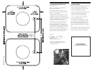
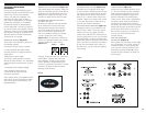
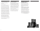
POWERED SUBWOOFER
The RM7500 System uses a specially
finished Polk Audio PSW650 Powered
Subwoofer to round out its surround sound
capabilities. This subwoofer module may be
placed behind furniture or next to a sofa or
chair. It can be placed anywhere in the room,
but you will get the best performance from
it when it is on the same side of the room
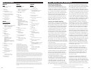
as the front satellites. Placing it near a wall
(good) or in a corner (better) enhances its
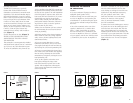
delivery of lower frequencies. Allow at least
6 inches (15cm) of space between any
subwoofer driver and any wall or obstruc-
tion. (Figure 2)
Set the subwoofer on its feet. (Figure 3)
NEVER LAY THE SUBWOOFER ON THE
AMPLIFIER END–THIS WILL DAMAGE
THE AMPLIFIER.
This subwoofer is not magnetically shielded
and should not be placed close to a television
set. If you see any color distortion on your
TV, move the subwoofer away from the set.
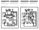
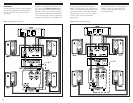
WALL-MOUNTING THE SATELLITES
All five satellites of the RM7500 system have
integrated wall-mounting brackets built onto
the rear of each speaker. On-wall installation
of the RM speakers requires basic skills and
basic tools (drill and screwdriver). If you are
in doubt that you possess the necessary
skills or tools, consult your Polk dealer or a
professional installer. Otherwise, follow the
steps below to safely secure the speakers
to the location of your choice.
• Make sure the locations you have selected
for wall-mounting do not conceal electrical
wiring or plumbing.
• Hold the speaker in the chosen location to
make certain it clears the ceiling, adjacent
walls, corners, beams, lighting fixtures and
door/window frames.
• If you are certain that there is a stud
behind the wall surface, drive a #10 screw
(not supplied) through the wall and into the
stud leaving the screw head protruding 1/8".
• If there is no stud behind the chosen loca-
tion, install a #10 wall anchor (not supplied)
into the wall by following the wall anchor
manufacturer’s directions, leaving the screw
head protruding 1/8".
• Line up the speaker so that the screw
head passes through the large center
hole of the bracket’s keyhole slot. Let the
speaker slide straight down, allowing the
screw head to slip behind the smaller end
of the keyhole slot.
CONNECTING THE SPEAKERS
TO YOUR SYSTEM
GENERAL
• Use two-conductor 16-gauge (or thicker)
audiophile grade speaker wires.
• Measure enough wire to reach from your
receiver or amplifier to each speaker plus
an additional 12" to allow moving the speak-
ers or receiver without having to disconnect
the wires.
• One of the terminals on the rear of the
speaker is marked red (+) and the other
black (-). Make certain that you connect
the wire from the red (+) terminal of your
receiver or amplifier to the red (+) terminal
on your speaker, and the wire from the black
(-) terminal of your receiver or amplifier to
the black (-) terminal on your speaker. Most
wire has some indication (such as color
code, ribbing, or writing) on one of the two
conductors to help maintain consistency.
• If your speakers sound “thin,” with
little bass and little or no center image,
chances are that one of the speakers
wires is connected backwards. Double-
check all connections.
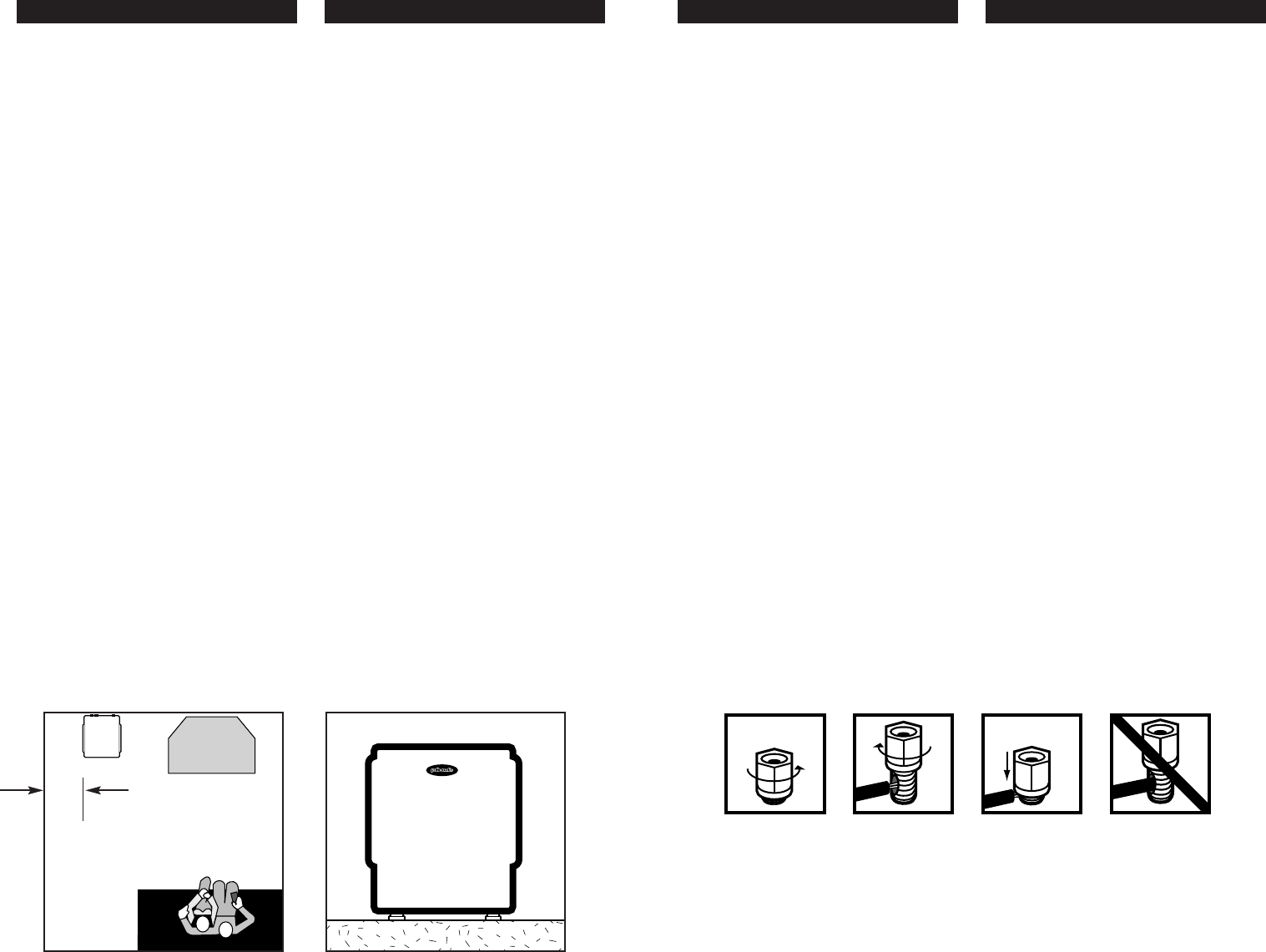
To connect wire to the binding post, unscrew
the plastic hex nut on the binding post and
insert the bare wire into the hole near the
base of the binding post. Do not insert the
insulated part of the wire into the hole; this
will not give you a good connection. Twist the
hex nut back down the binding post until it
firmly meets the wire. Do not over-tighten.
(Figure 4)
FIGURE 3
OK
FIGURE 2
Driver Side
≥
6 inches (15cm)
From wall
FIGURE 4
LOOSEN HEX NUT INSERT SPEAKER WIRE TIGHTEN HEX NUT DO NOT INSERT
THROUGH HOLE INSULATED SECTION
OF SPEAKER WIRE