


2 Contact Polk Audio Customer Service 1-800-377-7655, polkcs@polkaudio.com
GETTING STARTED
The RM6000 System carton should contain the following items:
Four (4) magnetically shielded satellite speakers
One (1) magnetically shielded center channel speaker
One (1) Powered Subwoofer
Five (5) sets of four (4) “Bump Ons” (adhesive rubber feet), 20 total
One (1) warranty card
Please inspect each loudspeaker carefully. Notify your Polk Audio dealer if you notice any difference, damage, or any missing items. Keep the
carton and packing material. They will do the best job of protecting your speakers if they need to be transported.
SPEAKER PLACEMENT
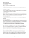
CENTER CHANNEL SPEAKER (Figure 1)
Place the center channel speaker as close to your TV as possible in order to “anchor” dialogue and effects to the screen area. The most popular
placement for a center channel speaker is right on top of your TV set. It is also fine to place below the TV or on the wall directly above the TV;
use the convenient keyhole slots on the rear of the speaker (see next section).
FRONT SATELLITES (Figure 2)
To provide ideal imaging, try to place the front satellites to the left and right of your TV about as far apart as the distance you are sitting from
them. Avoid placing them less than 2 feet (60cm) from the side walls of the room. RM Satellites will sound great mounted on the wall on stands,
bookshelves, or in entertainment centers. RM6000 satellites are easy to mount onthe wall using convenient keyhole slots built right in the back
of the speakers. When mounting the speakers on stands or on a shelf, place them at or near your ear level. (Speaker stands appropriate for the
RM6000 satellites are available at your Polk Audio dealer or in the Polk Webstore at www.polkaudio.tranguard.com.)
SURROUND SPEAKERS (Figures 3a, 3b)
The best placement for surround channel speakers is on the side walls, facing each other, a foot or two behind your listening position. If this
placement is not possible, the speakers may be placed on a rear wall. In either case, mount the speakers two to four feet (60-120cm) above your
head (when seated).
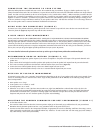
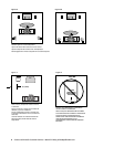
POWERED SUBWOOFER (Figures 4, 5)
The RM6000 System includes a Powered Subwoofer to enhance bass and really add punch to your home theater. This subwoofer may be placed
inside an entertainment center, behind furniture or next to a sofa or chair. It can be placed anywhere in the room, but you will get the best per-
formance from it when it is on the same side of the room as the front satellites. Placing it near a wall or in a corner will increase bass loudness.
Allow at least 6 inches (15cm) of space between the subwoofer driver and a wall or obstruction. It may lie on its side, but NEVER LAY THE SUB-
WOOFER ON THE AMPLIFIER END – THIS WILL DAMAGE THE AMPLIFIER (Figure 5). This subwoofer is not magnetically shielded and should not
be placed close to a television set. If you see any color distortion on your TV, move the subwoofer away from the set.
For more detailed subwoofer placement and set-up advice go to http://www.polkaudio.com/home/faqad/.
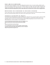
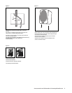
WALL-MOUNTING THE SATELLITES AND CENTER SPEAKER (FIGURES 6, 7)
For easy, safe and secure installation, RM Series Satellite and Center Channel Speakers have keyhole slots incorporated into their design (2 on
the back of the Center Channel and 1 on the back of the Satellites). On-wall installation of RM speakers requires basic skills and basic tools
(drill and screwdriver). If you are in doubt that you possess the necessary skills or tools, consult your Polk dealer or a professional installer.
Otherwise, grab your tools and follow the steps below to safely secure the speakers to the location of your choice.
Make sure the locations you have selected for wall-mounting do not conceal electrical wiring or plumbing.
Hold the speaker in the chosen location to make certain it clears the ceiling, adjacent walls, corners, beams, lighting fixtures and
door/window frames.
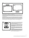
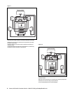
If you are certain that there is a stud behind the wall surface, drive a #10 screw (not supplied) through the wall and into the stud leaving
the screw head protruding 1/8” (4mm) (Figure 6a)
If there is no stud behind the chosen location, install a #10 wall anchor (not supplied) into the wall by following the wall anchor
manufacturer’s directions, then insert a #10 screw (not supplied), leaving the screw head protruding 1/16” (1.6mm) (Figure 6b).
For masonry walls, use a masonry drill bit and #10 masonry anchor and screw (not included).
Line up the speaker so that the screw head passes through the large center hole of the keyhole slot. Let the speaker slide straight down,
allowing the screw head to slip behind the smaller end of the keyhole slot (Figure 7).
If you require more flexibility, use an optional fully articulating “ball and socket” type mounting bracket such as the Series 25 RST by
Omnimount, available at your Polk Audio dealer or in the Polk Webstore at www.polkaudio.tranguard.com.