


Other connections
08
52
En
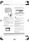
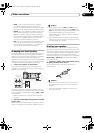
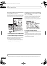
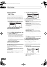
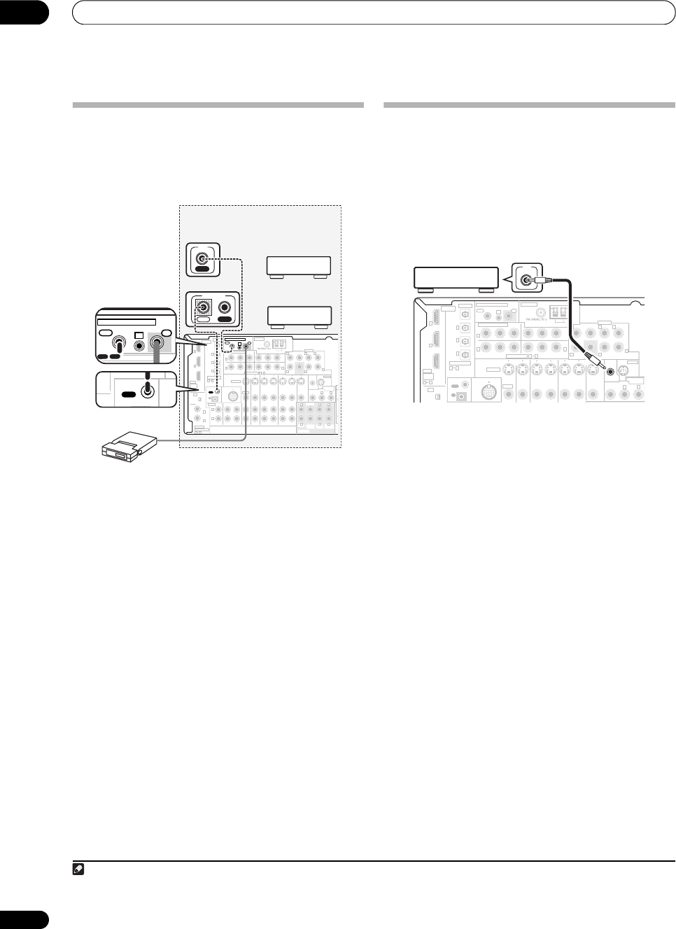
Connecting an IR receiver
If you keep your stereo components in a closed cabinet or
shelving unit, you can use an optional IR receiver (such
as a Niles or Xantech unit) to control your system instead
of the remote sensor on the front panel of this receiver.
1
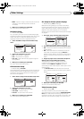
1 Connect the IR receiver sensor to the MULTI-ZONE &
SOURCE IR IN jack on the rear of this receiver.
2 Connect the IR IN jack of another component to the
MULTI-ZONE & SOURCE IR OUT jack on the rear of this
receiver to link it to the IR receiver.
Please see the manual supplied with your IR receiver for
the type of cable necessary for the connection.
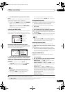
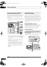
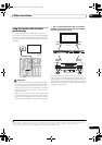
• If you want to link a Pioneer component to the IR
receiver, see Operating other Pioneer components
with this unit’s sensor on page 65 to connect to the
CONTROL jacks instead of the IR OUT jack.
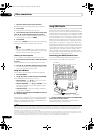
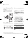
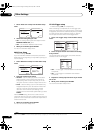
Switching components on and off using
the 12 volt trigger
You can connect a component in your system (such as a
screen or projector) to this receiver so that it switches on
or off using a 12 volt trigger when you select an input
function. However, you must specify which input
functions switch on the trigger using the 12 Volt Trigger
setup on page 58. Note that this will only work with
components that have a standby mode.
• Connect the 12 V TRIGGER jack of this receiver to
the 12 V trigger of another component.
Use a cable with a mono mini-plug on each end for the
connection.
• The trigger maximum power is DC OUT 12 V/50 mA.
After you’ve specified the input functions that will switch
on the trigger, you’ll be able to switch the component on
or off just by pressing the input function(s) you’ve set in
12 Volt Trigger setup on page 58.
Note
1 • Remote operation may not be possible if direct light from a strong fluorescent lamp is shining on the IR receiver remote sensor window.
• Note that other manufacturers may not use the IR terminology. Refer to the manual that came with your component to check for IR compatibility.
• If using two remote controls (at the same time), the IR receiver’s remote sensor takes priority over the remote sensor on the front panel.
Closet or shelving unit
IR receiver
(
Single
)
CD
IN IN IN IN IN INOUT OUT OUT
IN IN IN IN MONITOR
OUT
OUT OUT
CD-R/TAPE/MD DVD/LD
DVR/VCR1 DVR/VCR2
TV/SAT
CONTROL
AUDIO
ANTENNA
AM LOOP
Y
P
B
P
R
Y
P
B
P
R
Y
P
B
P
R
Y
P
B
P
R
DIGITAL
ASSIGNABLE
OPTICAL
COAXIAL
VIDEO
S-VIDEO
PRE OUT
COMPONENT VIDEO
OUT
HDMI
XM
ASSIGNABLE
OUT
(
TV/SAT
)
(
DVD/LD
)
(
CD
)
(
DVR/
VCR1
)
IN
OUT
IN
1
IN
1
(
TV/SAT
)
IN
2
IN
1
IN
2
IN
3
(
DVD/LD
)
IN
1
(
DVR/VCR2
)
IN
2
IN
2
IN
3
31
R
L
R
R R
R
R R
L L
L LL
L
OUT
IN
ASSIG-
NABLE
21
21
ASSIGNABLE
31
CENTER
CENTER
MULTI CH IN
FRONT
FRONT
SUR-
ROUND
SUR-
ROUND
SURROUND BACK
SURROUND
BACK
SUB
WOOFER
SUB
WOOFER
OUT
IR
IN
MULTI-ZONE & SOURCE
ZONE 2
iPod
IN
IN
MONITOR
OUT
12V
TRIGGER
(DC OUT 12V/
50mA MAX)
ZONE 2
MULTI-ZONE
& SOURCE
SIRIUS
R
L
CONTROL
OUT
iPod
IN
ANTENNA
COMPONENT VIDEO
OUT
IR
IN
MULTI-ZONE & SOURCE
ZONE 2
Non-Pioneer
component
IN
IR
Pioneer
component
IN OUT
CONTROL
(
Single
)
IN IN IN IN MONITOR
OUT
OUT OUT
CONTROL
ANTENNA
AM LOOP
Y
P
B
P
R
Y
P
B
P
R
Y
P
B
P
R
Y
P
B
P
R
DIGITAL
OPTICAL
VIDEO
S-VIDEO
PRE OUT
COMPONENT VIDEO
OUT
HDMI
XM
ASSIGNABLE
OUT
(
TV/SAT
)
(
DVD/LD
)
(
CD
)
(
DVR/
VCR1
)
IN
OUT
IN
1
IN
1
(
TV/SAT
)
IN
2
IN
1
IN
2
IN
3
IN
2
IN
3
31
R R
R
L LL
OUT
IN
ASSIG-
NABLE
21
ASSIGNABLE
31
CENTER
FRONT
SUR-
ROUND
SURROUND BACK
SUB
WOOFER
OUT
IR
IN
MULTI-ZONE & SOURCE
ZONE 2
iPod
IN
IN
MONITOR
OUT
12V
TRIGGER
(DC OUT 12V/
50mA MAX)
ZONE 2
MULTI-ZONE
& SOURCE
SIRIUS
R
L
12V
TRIGGER
VSX-90TXV_KU.book Page 52 Friday, March 16, 2007 5:46 PM