


En
23
03
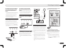
Connecting your equipment
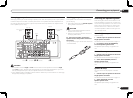
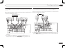
% Switch the receiver into standby then
use the supplied iPod cable to connect
your iPod to the iPod iPhone iPad USB
terminal on the front panel of this
receiver.
! It is also possible to connect using the cable
included with the iPod, but in this case it is not
possible to view pictures via the receiver.
! For the cable connection, also refer to the
operating instructions for your iPod.
! For instructions on playing the iPod, see
Playing an iPod on page 29 .
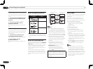
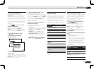
Connecting a USB device
It is possible to play audio and photo files by
connecting USB devices to this receiver. It
is also possible to connect a USB keyboard
(US-international layout) to the receiver to enter
text in the following GUI screens.
! Change the input name in the Input Setup
menu (page 27).
! Add names to radio station presets (page 32).
USB
HDMI 3 INPUT
iPod iPhone iPad
AUTO SURR/ALC/
STREAM DIRECT
STANDARD
SURROUND
ADVANCED
SURROUND
iPod iPhone iPad
DIRECT CONTROL
5V 2.1
A
USB mass
storage device
USB keyboard
% Switch the receiver into standby
then connect your USB device to the
USB terminal on the front panel of this
receiver.
! This receiver does not support a USB hub.
! For instructions on playing the USB device,
see Playing a USB device on page 30 .
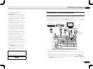
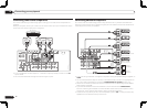
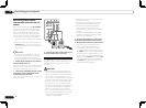
Connecting an HDMI-equipped
component to the front panel
input
Video camera (etc.)
USB
HDMI 3 INPUT
iPod iPhone iPad
AUTO SURR/ALC/
STREAM DIRECT HOME THX
STANDARD
SURROUND
ADVANCED
SURROUND
iPod iPhone iPad
DIRECT CONTROL
5V 2.1
A
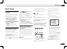
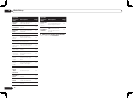
Connecting to a wireless LAN
Wireless connection to the network is possible
through a wireless LAN connection. Use the
separately sold AS-WL300 for connection.
! For instructions on setting the wireless LAN
converter, see Network Setup menu on page
68 .
WAN
DC 5V WPS
Ethernet
L
R
2
PRE OUT
O
OFER
2
SURROUND SURR BACK
FH / FW
(
CD
)
L
BLE
IN
2
(
DVR/BDR
)(
TV/SAT
)
OPTICAL
ASSIGNABLE
IN
1
IN
2
IN
3
OUT
(
VIDEO
)
(
OUTPUT 5
V
0.1 A MAX
)
ADAPTER PORT
DC OUTPUT
for WIRELESS LAN
(
10/100
)
LAN
(
OUTPUT
5 V
0.6 A MAX
)
SURROUND BACK
L
R L
R
L
(
Single
)
(
Single
)
FRONT HEIGHT / FRONT WIDE /
B
Internet
Modem
Wireless LAN converter (AS-WL300)
Router
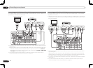
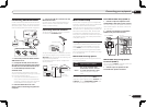
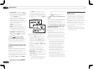
Connecting an IR receiver
If you keep your stereo components in a closed
cabinet or shelving unit, or you wish to use the
sub zone remote control in another zone, you
can use an optional IR receiver (such as a Niles
or Xantech unit) to control your system instead
of the remote sensor on the front panel of this
receiver.
! Remote operation may not be possible if direct
light from a strong fluorescent lamp is shining
on the IR receiver remote sensor window.
! Note that other manufacturers may not use
the IR terminology. Refer to the manual that
came with your component to check for IR
compatibility.
! If using two remote controls (at the same
time), the IR receiver’s remote sensor takes
priority over the remote sensor on the front
panel.
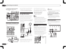
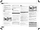
1 Connect the IR receiver sensor to the IR
IN jack on the rear of this receiver.
RS-232C
ZONE 2
IN IN IN
DVR/
OUTOUT
TV/SAT VIDEODVD
COMPONENT VIDEO
Y P
B
P
R
ASSIGNABLE
MONITOR
OUT
(
DVD
)
IN
1
(
DVR/
BDR
)
IN
2
EXTENSION
FRON
T
R
SPEAKERS
A
FM UNBAL 75
AM LOOP
ANTENNA
(
OUTPUT 5 V
150 mA MAX
)
CONTROL IR
OUT
IN
OUT
IN
HDMI
BD IN
(VIDEO)
IN
1
IN
2
IN
4
IN
5
(DVD)
ASSIGNABLE
1 6
IN
IR
IN OUT
CONTROL
Closet or shelving unit
Pioneer
component
Non-Pioneer
component
IR receiver
2 Connect the IR IN jack of another
component to the IR OUT jack on the rear
of this receiver to link it to the IR receiver.
Please see the manual supplied with your IR
receiver for the type of cable necessary for the
connection.
! If you want to link a Pioneer component to
the IR receiver, see Operating other Pioneer
components with this unit’s sensor on page
24 to connect to the CONTROL jacks instead
of the IR OUT jack.