


6
En
OPTICAL
R
L
R
L
CD
L
R
CONTROL
OUT
OPTICAL
DIGITAL IN
IN OUT
DIGITAL
OUT
LINE OUT
CONTROL
L
R
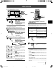
C System remote control with a Pioneer stereo
amplifier that has the Î mark(PD-F407 only)
When a Pioneer stereo amplifier bearing the Î mark is used,
connect the CONTROL IN jack on the rear panel of the CD player
to the CONTROL OUT jack of the amplifier. This will enable the
CD player to be controlled using the remote control unit supplied
with the stereo amplifier. If you do not plan to use this feature, it
is not necessary to connect the CONTROL IN/OUT jacks.
÷ The remote control unit supplied with the amplifier can be used
to control Play, Stop, Pause, Track/Disc Search and Disc Change
operations.
÷ For instructions regarding connections and operation, refer to
the operating instructions provided with your stereo amplifier.
NOTES:
÷
When a control cable is connected to the player’s CONTROL
IN jack, direct control of the player with the remote control unit
is not possible. Operate the player with the remote control unit
by aiming it at the amplifier.
÷
Be sure to connect both of the control cable's plugs securely to
the CONTROL IN and CONTROL OUT jacks. Do not connect
only one end of the cable.
÷
Be sure to turn off the power of the amplifier before connecting
the power cord and output cable.
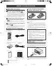
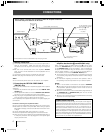
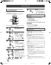
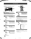
A Making connections
1 Connect the OUTPUT jacks of this unit to the input jacks (CD or
AUX) of the amplifier. Make sure that the white plug is
connected to the left (L) jack and the red plug to the right (R)
jack.
÷ Be sure not to connect this unit to the amplifier’s PHONO
jacks, as sound will be distorted and normal playback will not
be possible.
2 Connect the power cord to a household AC wall outlet.
÷ Make sure plugs are inserted fully into the wall outlet.
NOTE:
Do not connect the power cord to an AC outlet on your amplifier.
A-1
Output cable
White
Red
White
Red
C
CD player
Power cord
A-2
=
To the CONTROL IN jack
of the Pioneer component
bearing the Î mark.
( PD-F407 only)
C
IN
Optical Fiber Cable
OUT
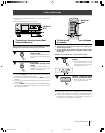
B Connecting the OPTICAL FIBER CABLE
(PD-F507 only)
This unit can be connected to an amplifier equipped with an optical
digital jack.
1. Remove the protective dust cap from this unit’s DIGITAL OUT
OPTICAL jack.
2. Use an optical fiber cable to connect the DIGITAL OUT OPTICAL
jack of this unit to the optical input jack of the amplifier.
÷ Align the plug of the optical fiber cable with the optical digital jack
and fully insert the plug to make a secure connection.
Use a separately sold optical fiber cable for the optical digital jack
connections.
Precautions concerning use of optical fiber cables
÷ Fully insert the optical fiber cable plugs all the way into the jacks.
÷ Be careful not to fold or crimp the cable. When coiling an optical
fiber cable for storage, make sure the diameter of the coil is 15 cm
or larger.
÷ Use an optical fiber cable with a length of 3 m or less.
÷ Protect the optical fiber cable plugs from scratches and dust.
÷ When the unit is not connected using an optical fiber cable, be sure
to keep the protective dust cap plugged into the optical digital
output jack at all times.
POWER-CORD CAUTION
Handle the power cord by the plug. Do not pull out the plug by
tugging the cord and never touch the power cord when your hands
are wet as this could cause a short circuit or an electric shock. Do
not place the unit, a piece of furniture, etc., on the power cord, or
pinch the cord. Never make a knot in the cord or tie it with other
cords. The power cords should be routed such that they are not
likely to be stepped on. A damaged power cord can cause a fire or
give you an electrical shock. Check the power cord once in a while.
When you find it damaged, ask your nearest PIONEER authorized
service center or your dealer for a replacement.
CONNECTIONS
Plug into the wall
outlet at last.
Control cable ( PD-F407 only)
Stereo amplifier
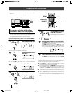
CONNECTIONS
÷ Before making or changing the connections, switch off the power switch and
disconnect the power cord from the AC outlet.
This output terminal is
PD-F507 only.
B
The illustration shows the flat blade 2-pin AC plug model.
PRE1297-A/En/02-08 04.1.6, 11:29 AM6