++
≠≠
++
++
≠≠
≠≠
+
≠
+
≠
+
≠
+
≠
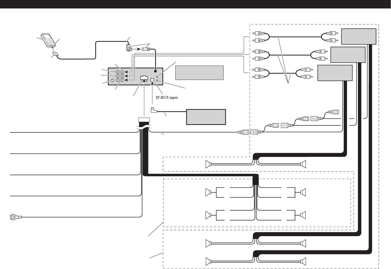
Power amp
(sold separately)
Subwoofer
Yellow
Connect to the constant 12 V supply terminal.
Red
Connect to terminal controlled by ignition switch (12 V DC).
Orange/white
Connect to lighting switch terminal.
Connect with RCA cables
(sold separately)
Rear speaker
Perform these connections when
using the optional amplifier.
Yellow/black
If you use an equipment with Mute function, wire this lead to the Audio
Mute lead on that equipment. If not, keep the Audio Mute lead free of any
connections.
Use a stereo mini plug cable
to connect with auxiliary
e
q
ui
p
ment
.
Black (chassis ground)
Connect to a clean, paint-free metal location.
iPod with Dock
Connector
Dock connector port
Dock connector
Interface cable (e.g., CD-I200)
(sold separately)
2 m (6 ft. 7 in.)
This product
Rear output
Front output
Antenna jack
Subwoofer output
Fuse (10 A)
AUX jack (3.5 ø)
(Blue)
IP-BUS cable
Multi-CD player
(sold separately)
System remote control
Front speaker Front speaker
Left Right
Rear speaker
Subwoofer
15 cm (5-
7/8 in.)
Gray
Blue/white
Connect to system control terminal of the power
amp or auto-antenna relay control terminal (max.
300 mA 12 V DC).
With a 2 speaker system, do not connect
anything to the speaker leads that are not
connected to speakers.
Front speaker Front speaker
Rear speaker Rear speaker
White Gray
Gray/blackWhite/black
Green Violet
Green/black Violet/black
Wired remote in
p
u
t
H
ar
d
-wire
d
remote control
ada
p
tor can be connected (sold
se
p
aratel
y
)
.
Power amp
(sold separately)
Power amp
(sold separately)
Connecting the Units
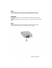
7 When not connecting a rear speaker lead to a
Subwoofer


