


Connections
WARNING
! Use speakers over 50 W (output value) and be-
tween 4 W to 8 W (impedance value). Do not
use 1 W to 3 W speakers for this unit.
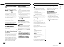
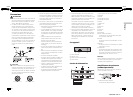
! The black cable is ground. When installing
this unit or power amp (sold separately), make
sure to connect the ground wire first. Ensure
that the ground wire is properly connected to
metal parts of the car’s body. The ground wire
of the power amp and the one of this unit or
any other device must be connected to the car
separately with different screws. If the screw
for the ground wire loosens or falls out, it
could result in fire, generation of smoke or
malfunction.
Ground wire
Metal parts of car’s body
POWER AMP
Other devices
(Another electronic
device in the car)
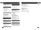
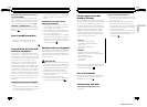
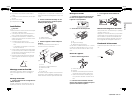
Important
! When installing this unit in a vehicle without
an ACC (accessory) position on the ignition
switch, failure to connect the red cable to the
terminal that detects operation of the ignition
key may result in battery drain.
O
N
S
T
A
R
T
O
F
F
ACC position No ACC position
! Use this unit with a 12-volt battery and nega-
tive grounding only. Failure to do so may result
in a fire or malfunction.
! To prevent a short-circuit, overheating or mal-
function, be sure to follow the directions
below.
— Disconnect the negative terminal of the
battery before installation.
— Secure the wiring with cable clamps or ad-
hesive tape. Wrap adhesive tape around
wiring that comes into contact with metal
parts to protect the wiring.
— Place all cables away from moving parts,
such as the gear shift and seat rails.
— Place all cables away from hot places,
such as near the heater outlet.
— Do not connect the yellow cable to the bat-
tery by passing it through the hole to the
engine compartment.
— Cover any disconnected cable connectors
with insulating tape.
— Do not shorten any cables.
— Never cut the insulation of the power cable
of this unit in order to share the power
with other devices. The current capacity of
the cable is limited.
— Use a fuse of the rating prescribed.
— Never wire the negative speaker cable di-
rectly to ground.
— Never band together negative cables of
multiple speakers.
! When this unit is on, control signals are sent
through the blue/white cable. Connect this
cable to the system remote control of an exter-
nal power amp or the vehicle’s auto-antenna
relay control terminal (max. 300 mA 12 V DC).
If the vehicle is equipped with a glass anten-
na, connect it to the antenna booster power
supply terminal.
! Never connect the blue/white cable to the
power terminal of an external power amp.
Also, never connect it to the power terminal of
the auto antenna. Doing so may result in bat-
tery drain or a malfunction.
En
10
Section
03
Installation
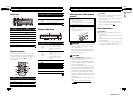
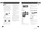
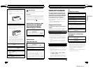
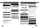
This unit
123 4
1 Antenna input
2 Fuse (10 A)
3 Power cord input
4 Rear output
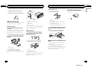
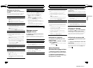
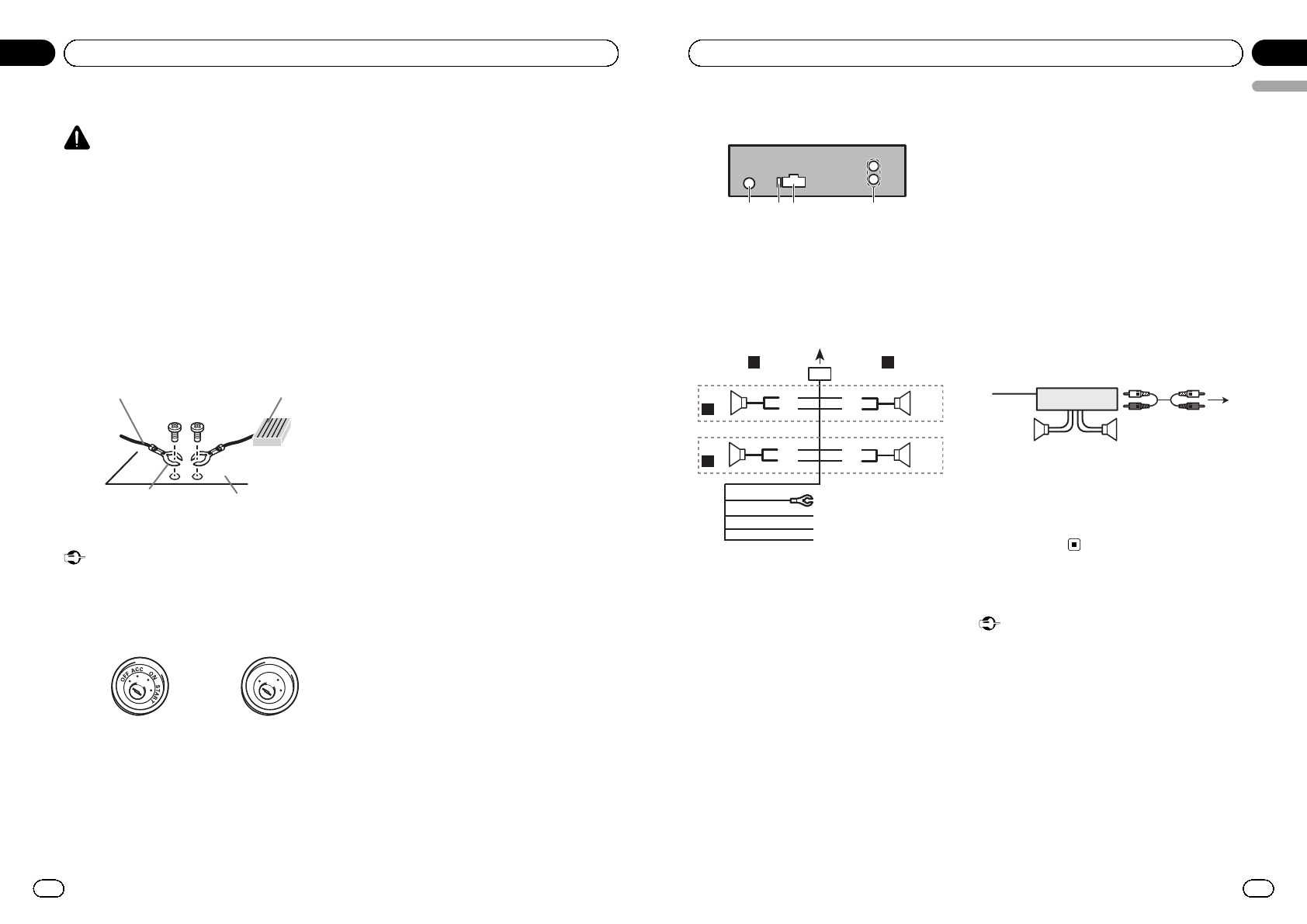
Power cord
1
8
9
c
d
6
32
4
5
7
a
b
e
f
h
g
LR
F
R
1 To power cord input
2 Left
3 Right
4 Front speaker
5 Rear speaker
6 White
7 White/black
8 Gray
9 Gray/black
a Green
b Green/black
c Violet
d Violet/black
e Black (chassis ground)
Connect to a clean, paint-free metal location.
f Yellow
Connect to the constant 12 V supply terminal.
g Red
Connect to terminal controlled by ignition
switch (12 V DC).
h Blue/white
Connect to system control terminal of the
power amp or auto-antenna relay control
terminal (max. 300 mA 12 V DC).
Note
With a 2 speaker system, do not connect anything
to the speaker leads that are not connected to
speakers.
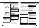
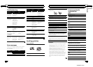
Power amp (sold separately)
Perform these connections when using the
optional amplifier.
1
4
2
55
3
1 System remote control
Connect to Blue/white cable.
2 Power amp (sold separately)
3 Connect with RCA cables (sold separately)
4 To Rear output
5 Rear speaker
Installation
Important
! Check all connections and systems before
final installation.
! Do not use unauthorized parts as this may
cause malfunctions.
! Consult your dealer if installation requires dril-
ling of holes or other modifications to the vehi-
cle.
! Do not install this unit where:
— it may inter fere with operation of the vehi-
cle.
— it may cause injury to a passenger as a re-
sult of a sudden stop.
En
11
English
Section
03
Installation
<QRD3061-A/N>6