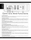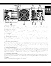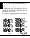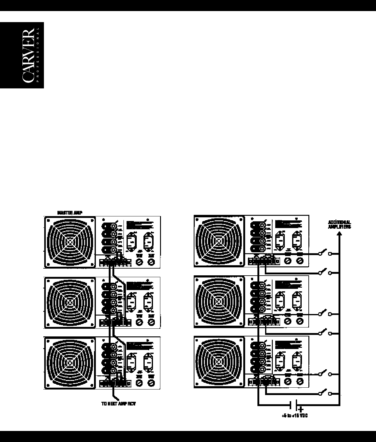
Fig. 3 shows a typical set up in a 3 rack with 3 amplifiers. In this case the top amplifier is the master
amplifier. Its channel 1 power switch controls the power up and power down sequence for the whole rack
and possibly additional racks. Channel 2 may be used as an optional backup for channel 1. All other
amplifiers have power switches turned off and sequence switches turned on.
Each amplifier channel controls the next amplifier channel in succession via an internally generated +11.4
VDC control voltage that is present at the (SND) terminal. In the unlikely event an amplifier should fail, the
amplifiers sequenced on after this unit will NOT turn off. The control voltage at the RCV terminal of the
failed amplifier will “carry through” the failed amplifier and keep the next amplifier on. Properly operating
amplifiers will not be taken out of service in a sequenced configuration by inoperative amplifiers. However,
if the master amplifier (channel 1 of the first amplifier) should fail, then the following amplifiers would power down.
Therefore, use channel 2 of the first amplifier as a backup to channel 1 by switching on both channel 1 and channel
two power switches. Channel 1 of the master amplifier may also be backed up by connecting a +DC control voltage
(battery) to it’s RCV terminal and ground. The rack shown below may also be turned on by a control voltage received
from another rack, or a control voltage from a remote location.
Remote Power Control
The rack shown in Figure 4 may be powered up and powered down from a remote location ie., mixing console or stage
position not located near the amplifiers. It is possible to control the amplifiers independently by removing the jumper
between channel 1 SND and channel 2 RCV terminals. This allows remote power on/off to an area or zone that a
particular channel is assigned to.
18
Figure 4Figure 3


