This is infinitely preferable to breaking the ground pin off the power cord. The pt1250’s XLR connector uses
the American wiring convention (pin 3 hot). Note that the pin 3 of the XLR connector corresponds to the tip
connection on the TRS phone jack. All input connectors are connected in parallel; you can parallel the
amplifier inputs by patching an unused input connector to its counterpart on the other channel.
For balanced operation:
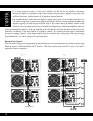
1/4-inch phone jack: Use a 3-conductor TRS 1/4” phone plug. The tip of the plug carries the (+, hot, non-
inverting) side of the signal, the ring carries the (–, low, inverting) side of the signal and the sleeve is ground.
XLR: Use a male XLR connector. Pin 2 carries the (+, hot, non-inverting) side of the signal, Pin 3 carries the
(–, low, inverting) side of the signal, and Pin 1 is ground.
For unbalanced operation:
1/4-inch phone plug: Use a 2-conductor (Tip-Sleeve) 1/4” phone plug. The tip of the plug carries the signal and the sleeve
is ground. The ring connection in the jack is automatically grounded by the sleeve. X L R : Pin 2 carries the (+, hot, non-
inverting) side of the signal, and Pin 1 is ground. Short Pin 3 to Pin 1 in order to reference the input differential amplifier
for the correct gain. N o t e : The gain remains the same regardless of whether the input is balanced or unbalanced. Note:
The polarity of the balanced inputs can be reversed by changing four jumpers located on the Input Board.
Output Wiring
Use heavy gauge wire for speaker connections. The greater the distance between the amplifier and the speakers, the
larger the diameter the wire should be to minimize power losses across the wire and improve the damping of the
speaker. Wire thickness specifications (or gauges) get larger as the wire gets thinner; thus 14-gauge wire is thicker than
16-gauge wire. Use the following as a guide: up to 25 ft. use 16 gauge, up to 40 ft. use 14 gauge, up to 60 ft. use 12
gauge, up to 100 ft. use 10 gauge, up to 150 ft. use 8 gauge, up to 250 ft. use 6 gauge.
This will insure that the resistance of the speaker wire is less than 5% of 4 ohms, resulting in a transmission loss of
less than 0.5 dB. The multi-way binding posts can accept spade lug, bare wire or banana connections. Be sure that all
the fine strands of the wire are twisted together and contained within the connector. If even one strand is loose and can
touch the adjacent terminal, a short circuit may result. Class I (NEC) wiring must be used.
For stereo operation, use the red and black binding posts associated with each channel. Unlike most solid-state
amplifiers, the pt1250 can be operated with its output connections paralleled.
CAUTION: Internal jumpers must be moved before this connection or operating mode is allowed. These
changes must be made at the Carver Professional factory, or by a qualified service technician.
Only the left input connections and level control are used in parallel mono mode. The minimum load impedance is two
ohms or greater. For driving a single load (which may be comprised of one or more speakers connected in series,
parallel, or series-parallel), the red binding posts must be wired in parallel (wired together) and the load connected to
either red and black binding posts. In either case, ensure that the total load impedance is not lower than that listed in
the specifications for the mode of operation that you have selected.
Polarity
Loudspeakers must be connected with consistent polarity for correct phasing between them. Incorrect phasing will do
no physical harm, but frequency response will be affected. The key is to make sure that both speakers connected to the
speaker terminals are hooked up the same way. Connect (–) at the speaker outputs to (–) on the back of the speaker,
and (+) at the speaker outputs to (+) on the back of the speaker.
13


