10
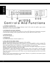
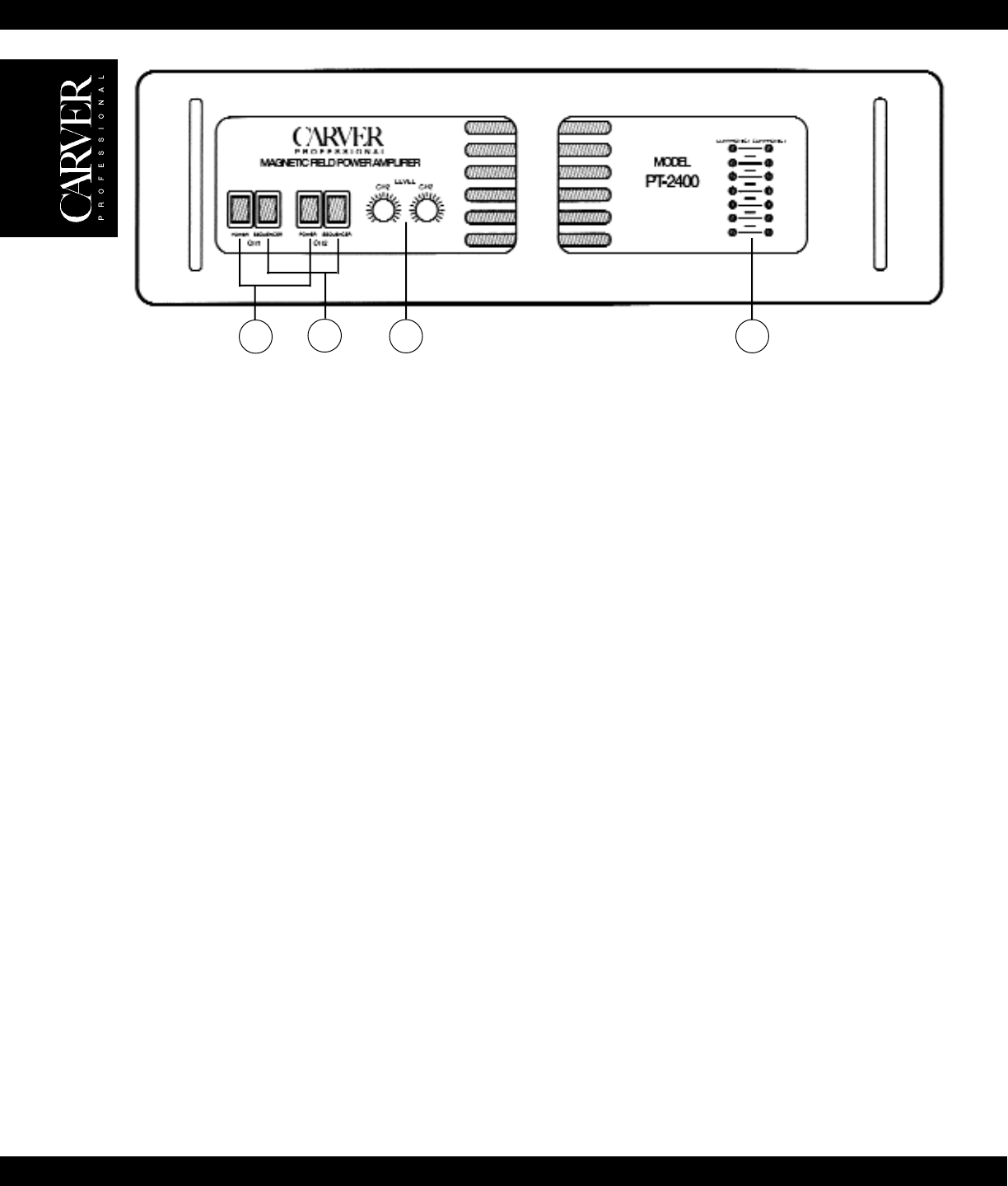
Controls And Functions
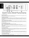
1. POWER SWITCHES
Channel 1 and Channel 2 power switches independently power up each channel. The slow start up feature of each
power supply allows both switches to be pushed simultaneously.
2. SEQUENCE SWITCHES
These switches make it possible to sequentially turn on and off amplifiers in one rack or multiple racks of units. A
group of amplifiers can be powered up with the power switch on a designated master amplifier or remotely via a +5
to +15 VDC voltage source. Two sequence switches allow remote power control of Channel 1 and Channel 2
independently.
3. LEFT AND RIGHT LEVEL CONTROLS
Eleven-step attenuators adjust the relative output level of the amplifier. The amount of attenuation corresponds to the
front panel markings, in dB. For maximum input sensitivity and signal to noise ratio at the input, set level controls for
full clockwise rotation.
4. CH1 /CH2 STATUS INDICATORS
These LEDs display information about the operation of the amplifier.
READY – These LEDs illuminate green when the power is on and the amplifier is ready to operate.
SIGNAL – These LEDs illuminate yellow to indicate the output voltage level of the amplifier in dB relative to the
maximum output.
CLIP/PROTECT – These LEDs illuminate red to indicate amplifier clipping, excessive high frequency protection, or
limiting by the clip eliminator option.
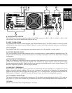
5. DUAL MONO SWITCH
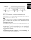
The Dual Mono Switch configures the input to allow both channels to be driven from a mono source via the channel
1 input. NOTE: channel 2 XLR connector may be used to patch to other amplifiers, if parallel connections are made
on the barrier block, ie. ch. 1 + connected to ch. 2 + etc.
6. SERIES MONO (BRIDGE) SWITCH
The Series Mono Switch inverts the phase of channel 1, which produces a differential voltage between Channel 1 red
(-) binding post and the Channel 2 red (+). Channel 1’s XLR and Barrier drive both channels. Minimum load
impedance in this configuration is 4 ohms.
7. CLIP ELIMINATOR SWITCH
The Clip Eliminator Switch enables circuitry which senses the onset of clipping and limits the output distortion to
approximately 1% for up to 8 dB of overdrive at the input.
21
3 4


