


Philips Semiconductors
TDA8946J
2 x 15 W stereo BTL audio amplifier
Product specification Rev. 02 — 14 March 2000 7 of 23
9397 750 06863
© Philips Electronics N.V. 2000. All rights reserved.
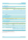
9. Limiting values
10. Thermal characteristics
11. Static characteristics
[1] With a load connected at the outputs the quiescent current will increase, the maximum of this increase being equal to the differential
output voltage offset (∆V
OUT
) divided by the load resistance (R
L
).
[2] The DC output voltage with respect to ground is approximately 0.5V
CC
.
[3] ∆V
OUT
= V
OUT+
− V
OUT−
Table 5: Limiting values
In accordance with the Absolute Maximum Rating System (IEC 60134).
Symbol Parameter Conditions Min Max Unit
V
CC
supply voltage no signal −0.3 +25 V
operating −0.3 +18 V
V
I
input voltage −0.3 V
CC
+ 0.3 V
I
ORM
repetitive peak output current - 2 A
T
stg
storage temperature non-operating −55 +150 °C
T
amb
operating ambient temperature −40 +70 °C
P
tot
total power dissipation - 28 W
V
CC(sc)
supply voltage to guarantee short-circuit
protection
-15V
Table 6: Thermal characteristics
Symbol Parameter Conditions Value Unit
R
th(j-a)
thermal resistance from junction to ambient in free air 40 K/W
R
th(j-mb)
thermal resistance from junction to mounting base both channels driven 4.5 K/W
Table 7: Static characteristics
V
CC
=18V; T
amb
=25
°
C; R
L
=8
Ω
; V
MODE
=0V; V
i
= 0 V; measured in test circuit Figure 14; unless otherwise specified.
Symbol Parameter Conditions Min Typ Max Unit
V
CC
supply voltage operating 6 18 25 V
I
q
quiescent supply current R
L
= ∞
[1]
- 2842mA
I
stb
standby supply current V
MODE
=V
CC
--10µA
V
O
DC output voltage
[2]
-9-V
∆V
OUT
[3]
differential output voltage offset - - 200 mV
V
MODE
mode selection input voltage operating mode 0 - 0.5 V
mute mode 3 - V
CC
− 1.5 V
standby mode V
CC
− 0.5 - V
CC
V
I
MODE
mode selection input current 0 < V
MODE
<V
CC
--20µA