


Philips Semiconductors
TDA8946J
2 x 15 W stereo BTL audio amplifier
Product specification Rev. 02 — 14 March 2000 19 of 23
9397 750 06863
© Philips Electronics N.V. 2000. All rights reserved.
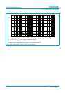
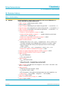
18. Revision history
Table 11: Revision history
Rev Date CPCN Description
02 20000314 - Product specification; second version; supersedes initial version TDA8946J-01 of
14 April 1999 (9397 750 04882). Modifications:
•
Table 1 on page 1: SVRR; Typ value 65 dB → added
•
Ordering options removed
•
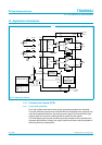
Figure 1 on page 2: Block diagram; pin numbers changed OUT2−→ 14 and OUT2+ → 17
•
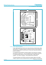
Figure 2 on page 3: Pin configuration; pin numbers changed OUT2−→14 and OUT2+ → 17
•
Table 3 on page 3: Pin description; pin numbers changed OUT2−→ 14 and OUT2+ → 17
•
Section 8 “Functional description”:
– Section 8.1 “Input configuration” on page 4 → added.
– Section 8.2 “Power amplifier” on page 5: ........, capable of delivering a peak output
current of 1.5 A → changed to 2 A.
– Section 8.2.1 “Output power measurement” on page 5 → added
– Section 8.2.2 “Headroom” on page 5 → added
•
Section 8.3 “Mode selection”:
– Standby mode: V
MODE
>(V
CC
− 0.5 V) → changed to (V
CC
− 0.5 V) < V
MODE
<V
CC
;
The power consumption of the TDA8946J will be reduced to <0.18 mW → added.
– Mute mode: the DC level of the input and output pins remain on half the supply
voltage → added;
– 2.5 V < V
MODE
<(V
CC
− 1.5 V) → changed to 3 V < V
MODE
<(V
CC
− 1.5 V)
– Section 8.3.1 “Switch-on and switch-off” on page 6 → added
•
Section 8.4 “Supply Voltage Ripple Rejection (SVRR)” on page 6 → added
•
Section 8.5 “Built-in protection circuits” on page 6 → added
•
Table 5 on page 7:
– P
tot
value added 28 W
– V
CC(sc)
value added 15 V
•
Table 6 on page 7:
– R
th(j-a)
value added 40 K/W
– R
th(j-c)
value 10 k/W → changed to R
th(j-mb)
value 4.5 K/W;
condition ‘in free air’ → changed to ‘both channels driven’
•
Table 7 on page 7: V
CC
: Max value 18 V changed to → 25 V; V
MODE
- mute mode - value
Min 2.5 → changed to 3 V
•
Table 8 on page 8:
– SVRR; Typ values 65 and 60 dB → added
– α
cs
; Typ value 75 dB → added
– R
source
changed to → R
S
in table and associated table notes; Value added R
S
=0Ω;
– Table note [2]: .... 100 mV (RMS).... changed to → ... 700 mV (RMS)....
•
Figure 3 to 13: figures added
•
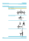
Section 13 “Internal circuitry” on page 13: → added
•
Figure 14: figure modified