


1998 Apr 01 4
Philips Semiconductors Product specification
2 × 1 W BTL audio amplifier TDA8542
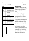
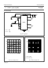
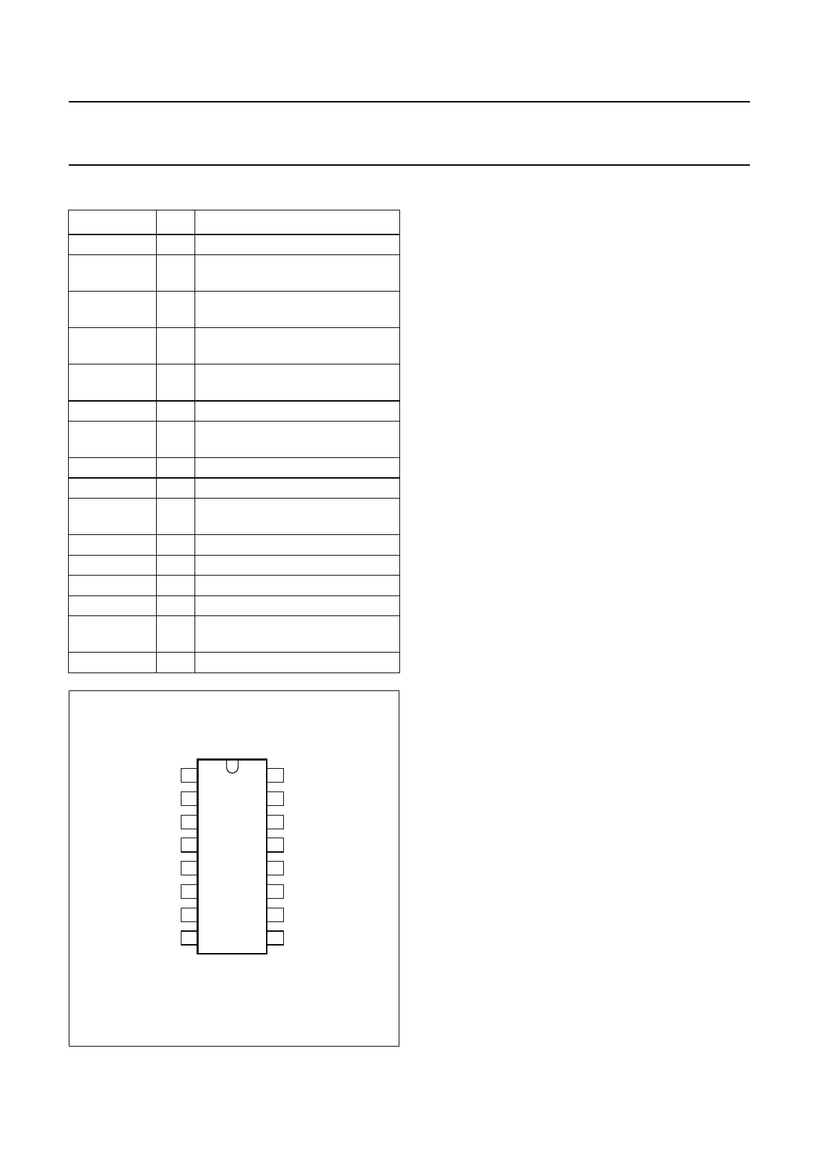
PINNING
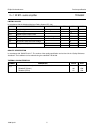
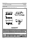
SYMBOL PIN DESCRIPTION
LGND 1 ground, left channel
OUTL+ 2 positive loudspeaker terminal,
left channel
MODE 3 operating mode select (standby,
mute, operating)
SVR 4 half supply voltage, decoupling
ripple rejection
BTL/SE 5 BTL loudspeaker or SE
headphone operation
n.c. 6 not connected
OUTR+ 7 positive loudspeaker terminal,
right channel
RGND 8 ground, right channel
V
CCR
9 supply voltage, right channel
OUTR− 10 negative loudspeaker terminal,
right channel
INR− 11 negative input, right channel
INR+ 12 positive input, right channel
INL+ 13 positive input, left channel
INL− 14 negative input, left channel
OUTL− 15 negative loudspeaker terminal,
left channel
V
CCL
16 supply voltage, left channel
Fig.2 Pin configuration.
handbook, halfpage
TDA8542
MGB974
1
2
3
4
5
6
7
8
16
15
14
13
12
11
10
9
LGND
OUTL+
MODE
SVR
BTL/SE
n.c.
OUTR+
RGND
V
CCR
OUTR−
INR−
INR+
INL+
INL−
OUTL−
V
CCL
FUNCTIONAL DESCRIPTION
The TDA8542(T) is a 2 × 1 W BTL audio power amplifier
capable of delivering 2 × 1 W output power to an 8 Ω load
at THD = 10% using a 5 V power supply. Using the MODE
pin the device can be switched to standby and mute
condition. The device is protected by an internal thermal
shutdown protection mechanism. The gain can be set
within a range from 6 dB to 30 dB by external feedback
resistors.
Power amplifier
The power amplifier is a Bridge Tied Load (BTL) amplifier
with a complementary PNP-NPN output stage.
The voltage loss on the positive supply line is the
saturation voltage of a PNP power transistor, on the
negative side the saturation voltage of a NPN power
transistor. The total voltage loss is <1 V and with a 5 V
supply voltage and an 8 Ω loudspeaker an output power of
1 W can be delivered.
Mode select pin
The device is in the standby mode (with a very low current
consumption) if the voltage at the MODE pin is
>(V
CC
− 0.5 V), or if this pin is floating. At a MODE voltage
level of less than 0.5 V the amplifier is fully operational.
In the range between 1.5 V and V
CC
− 1.5 V the amplifier
is in mute condition. The mute condition is useful to
suppress plop noise at the output caused by charging of
the input capacitor.
Headphone connection
A headphone can be connected to the amplifier using two
coupling capacitors for each channel. The common
GND pin of the headphone is connected to the ground of
the amplifier (see Fig.13). In this case the BTL/SE pin must
be either on a logic HIGH level or not connected at all.
The two coupling capacitors can be omitted if it is allowed
to connect the common GND pin of the headphone jack
not to ground, but to a voltage level of
1
⁄
2
V
CC
(see Fig.13).
In this case the BTL/SE pin must be either on a logic LOW
level or connected to ground. If the BTL/SE pin is on a
LOW level, the power amplifier for the positive
loudspeaker terminal is always in mute condition.