


1997 Jul 15 9
Philips Semiconductors Product specification
Stereo BTL audio output amplifier with DC
volume control
TDA7053A
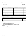
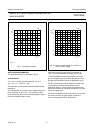
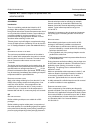
Fig.11 Input signal handling.
THD = 1 %.
handbook, halfpage
020
V
P
(V)
V
in
(V)
2.0
0
0.4
MBG665
0.8
1.2
1.6
4 8 12 16
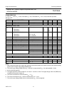
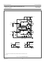
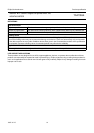
Fig.12 Volume control current as a function of
volume control voltage.
handbook, halfpage
0
I
VC
(µA)
2.0
V
VC
(V)
30
−10
−20
−30
20
10
0
MBG666
0.4 0.8 1.2 1.6
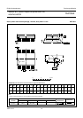
APPLICATION INFORMATION
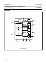
The application diagram is illustrated in Fig.13.
Test conditions
T
amb
=25°C unless otherwise specified; V
P
=6V;
V
DC
= 1.4 V; f
i
= 1 kHz; R
L
=8Ω.
The quiescent current has been measured without load
impedance.
The output power as a function of the supply voltage has
been measured at THD = 10%. The maximum output
power is limited by the maximum power dissipation and the
maximum available output current.
The maximum input signal voltage is measured at
THD = 1% at the output with a voltage gain of 0 dB.
To avoid instabilities and too high distortion, the input
ground and power ground must be separated as far as
possible and connected as close as possible to the IC.
The DC volume control can be applied in several ways.
Two possible circuits are shown below the main
application diagram. The circuits at the control pin will
influence the switch-on and switch-off behaviour and the
maximum voltage gain.
For single-end applications the output peak current must
not exceed 100 mA. At higher output currents the
short-circuit protection (MCL) will be active.