


1995 Feb 07 11
Philips Semiconductors Preliminary specification
Video output amplifier TDA6111Q
TEST AND APPLICATION INFORMATION
Dissipation
Regarding dissipation, distinction must first be made
between static dissipation (independent of frequency) and
dynamic dissipation (proportional to frequency).
The static dissipation of the TDA6111Q is due to high and
low voltage supply currents and load currents in the
feedback network and CRT.
The static dissipation equals:
R
fb
= value of feedback resistor.
I
oc
= DC value of cathode current.
With V
fb
=V
oc
= 100 V, R
fb
=68kΩ, I
oc
= 0.6 mA and
other typical conditions as mentioned in Chapter
“Characteristics”, the static dissipation P
stat
= 2.0 W.
P
stat
V
DDL
I
DDL
V
DDH
I
DDH
V
oc
I
oc
V
fb
V
fb
R
fb
--------
×–×+
×+×=
The dynamic dissipation equals:
P
dyn
=V
DDH
× (C
L
+C
fb
+C
int
) × f
i
× V
o(p-p)
×δ
C
L
= load capacitance.
C
fb
= feedback capacitance (≈ 150 fF).
C
int
= internal load capacitance (≈ 4 pF).
f
i
= input frequency.
V
o(p-p)
= output voltage (peak-to-peak value).
δ = non-blanking duty-cycle (≈ 0.8).
With C
L
= 10 pF, C
fb
= 0, C
int
= 4 pF, f
i
= 8 MHz
(simulation of worst-case noise), V
o(p-p)
= 100 V and
δ = 80% then P
dyn
= 1.8 W
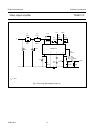
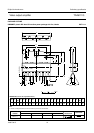
The IC must be mounted on the picture tube base print to
minimize the load capacitance (C
L
).
The total power dissipation, P
tot
=P
stat
+P
dyn
thus
amounts to 3.6 W under given conditions.
From T
j
=T
amb
+P
tot
× R
th j-a
<T
j(max)
= 150 °C, R
th j-a
of
the package and heatsink together must be < 24 K/W.