


July 1994 7
Philips Semiconductors Product specification
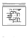
2 x 12 W hi-fi audio power amplifiers with
mute
TDA2616/TDA2616Q
Notes to the characteristics
1. V
P
= ±16 V; R
L
= 8 Ω; T
amb
= 25 °C; f = 1 kHz; symmetrical power supply I
MUTE
< 30 µA. See Fig.4
2. The power bandwidth is measured at an output power of P
O max
− 3 dB
3. The noise output voltage (RMS value) is measured at R
S
= 2 kΩ, unweighted (20 Hz to 20 kHz)
4. The ripple rejection is measured at R
S
= 0 and f = 100 Hz to 20 kHz. The ripple voltage (200 mV) is applied in phase
to the positive and the negative supply rails. With asymmetrical power supplies, the ripple rejection is measured at
f = 1 kHz
5. ±V
P
= 4 V; R
L
= 8 Ω; T
amb
= 25 °C; f = 1 kHz; symmetrical power supply. See Fig.4
6. V
P
= 24 V; R
L
= 8 Ω; T
amb
= 25 °C; f = 1 kHz; asymmetrical power supply I
MUTE
< 30 µA. See Fig.5
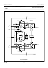
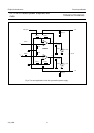
7. The internal network at pin 2 is a resistor devider of typical 4 kΩ and 5 kΩ to the positive supply rail. At the connection
of the 4 kΩ and 5 kΩ resistor a zener diode of typical 6.6 V is also connected to the positive supply rail. The spread
of the zener voltage is 6.1 to 7.1 V.
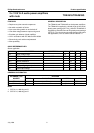
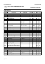
∆V
GND
DC output offset voltage − 40 200 mV
Operating position; note 6
I
P
total quiescent current 18 40 70 mA
P
O
output power
THD = 0.5% 5 6 − W
THD = 10% 6.5 8 − W
THD = 0.5%; R
L
= 4 Ω−10 − W
THD = 10%; R
L
= 4 Ω−14 − W
THD total harmonic distortion P
O
= 4 W − 0.13 0.2 %
B power bandwidth THD = 0.5%; note 2 − 40 to
20 000
− Hz
G
v
voltage gain 29 30 31 dB
G
v
gain unbalance − 0.2 1 dB
V
no
noise output voltage note 3 − 70 140 µV
Z
i
input impedance 14 20 26 kΩ
SVRR supply voltage ripple rejection 35 44 − dB
α channel separation − 45 − dB
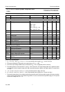
M
UTE POSITION (I
MUTE
≥ 300 µA)
V
O
output voltage V
I
= 600 mV − 0.3 1.0 mV
Z
2-7
mute input impedance note 7 6.7 9 11.3 kΩ
I
P
total quiescent current 18 40 70 mA
V
no
noise output voltage note 3 − 70 140 µV
SVRR supply voltage ripple rejection note 4 35 44 − dB
∆V
off
offset voltage with respect to operating
position
− 4 150 mV
I
2
current if pin 2 is connected to pin 5 −− 8.2 mA
SYMBOL PARAMETER CONDITIONS MIN. TYP. MAX. UNIT