


1998 Nov 18 6
Philips Semiconductors Product specification
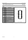
FM/IF amplifier/demodulator circuit TDA1576T
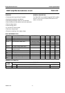
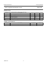
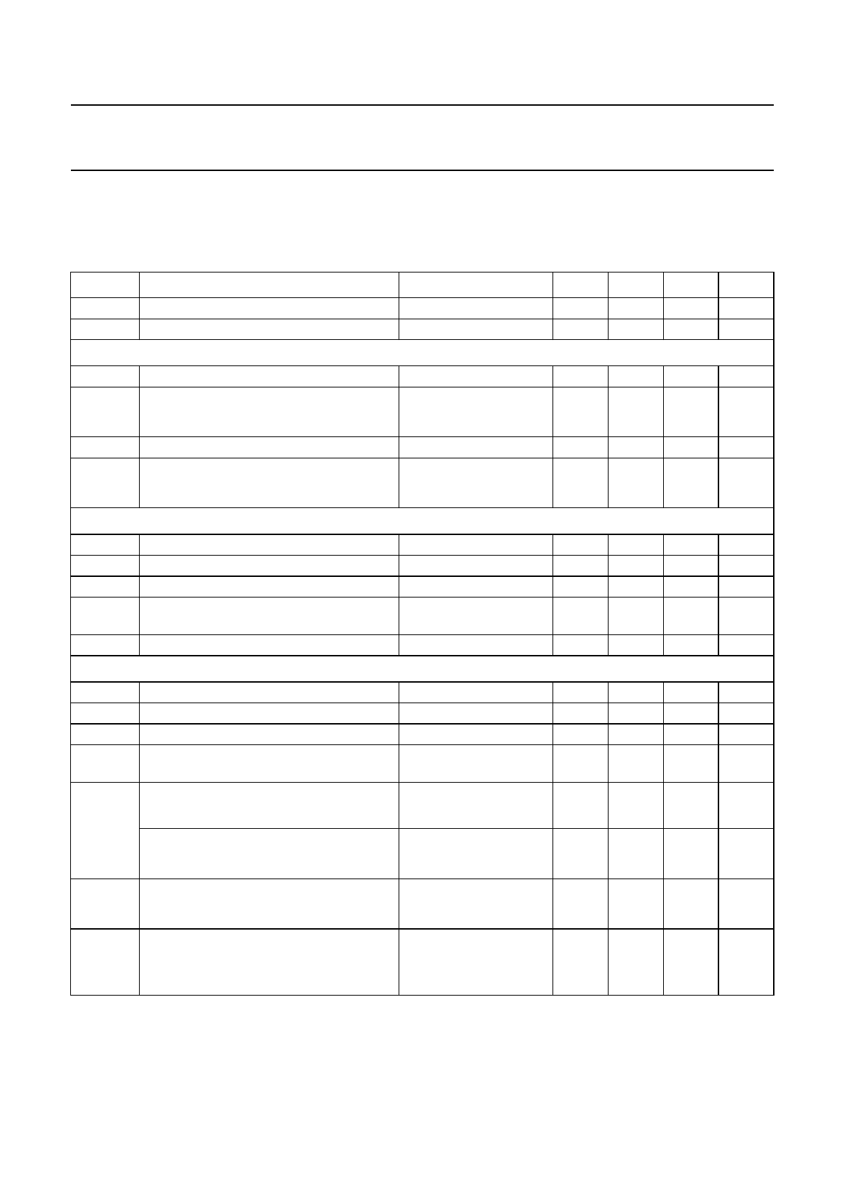
CHARACTERISTICS
V
P
= 8.5 V; f
IF
= 10.7 MHz; R
S
=60Ω; f
m
= 400 Hz with ∆f=±22.5 kHz; 50 µs de-emphasis (C
8-9
= 6.8 nF);
T
amb
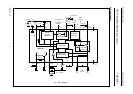
=25°C and measurements taken in Fig.1; unless otherwise specified. The demodulator circuit is adjusted at
minimum second harmonic distortion for V
iIF
= 1 mV and a deviation ∆f=±75 kHz.
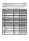
SYMBOL PARAMETER CONDITIONS MIN. TYP. MAX. UNIT
V
P
supply voltage (pin 1) 7.5 8.5 15 V
I
P
supply current V
5
=V
9
=V
13
= 0 10 16 23 mA
Reference voltage
V
ref
reference voltage (pin 14) I
14
= −1mA − 4.9 − V
∆V
ref
reference voltage dependence on
temperature
− 0.3 − %/K
I
14
maximum output current short-circuit current 4 6 7.5 mA
R
14
output resistor
I
14
< 1.2 mA − 60 150 Ω
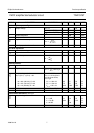
IF amplifier
V
iIF(rms)
input sensitivity (RMS value; pin 17) −3 dB before limiting 14 22 35 µV
R
17-18
input resistance V
iIF
= 200 mV (RMS) 10 −−kΩ
C
17-18
input capacitance V
iIF
= 200 mV (RMS) − 5 − pF
V
oIF(p-p)
output voltage at pins 3 and 7
(peak-to-peak value)
Z
3, 7
= 10 pF parallel to
1MΩ
610 680 750 mV
R
3-7
output resistance 200 250 300 Ω
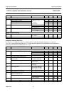
Demodulator
R
4-6
input resistance 20 30 40 kΩ
C
4-6
input capacitance − 1 2.5 pF
R
8, 9
output resistance 2.9 3.7 4.5 kΩ
V
8, 9
DC offset voltage on output pins at
V
4-6
=0
V
5
> 3 V or V
3-7
= 0 or
V
13
< 0.3 V
− 0 ±100 mV
demodulator efficiency − 40 − mV/°
demodulator efficiency dependent on
supply voltage
− 6.2 − mV/°
V/V DC voltage ratio 0.653 0.667 0.680 V/V
dependence on temperature − 10
−5
− 1/K
V
14
∆
V
14
T∆×
----------------------
V
14
∆
I
14
∆
------------
V∆
ϕ∆
-------
V
8-9
∆
ϕ∆
--------------
V
8-9
ϕ∆ V
P
3V
BE
–()
-----------------------------------------
V
8
V
9
+
2V
2
-------------------
V∆
T∆
-------
V
8
V
9
+
2V
2
-------------------
∆
T∆
-----------------------