


1998 Nov 18 11
Philips Semiconductors Product specification
FM/IF amplifier/demodulator circuit TDA1576T
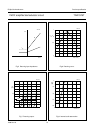
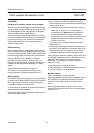
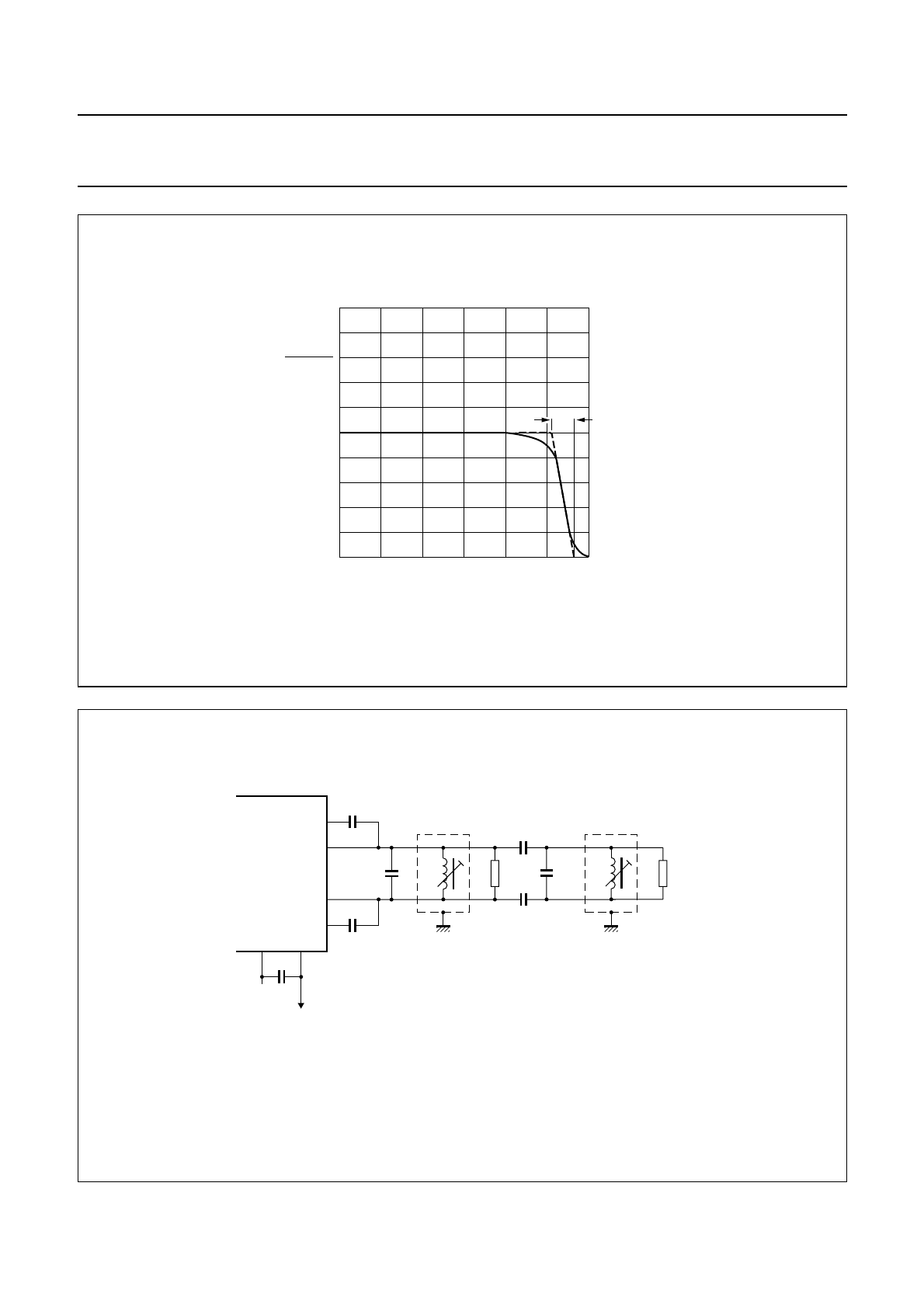
Fig.9 Standby switch.
handbook, halfpage
012
V
3-7
V
3-7 (max)
3
V
5
(V)
∆V
5
2
0
MEH148
1
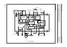
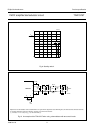
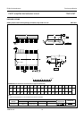
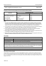
Fig.10 An example of the TDA1576T when using a demodulator with two tuned circuits.
Adjustment of the demodulator circuit is obtained with an IF signal which is higher than the 3 dB limiting level; L2 should be short-circuited or detuned;
L1 should be adjusted to minimum d
2
distortion, and then L2 to minimum d
2
distortion.
(1) Coil data: L1 = L2 = 0.38 µH; Q
o
= 70; coil former KAN (C).
handbook, full pagewidth
MBK240
L1
(1) (1)
1 kΩ
560
pF
560
pF
L2
390 Ω
39 pF
39 pF
33 pF
33 pF
C
8-9
V
oAF
98
7
6
4
3
TDA1576T